3 Operating the SAMMS-MV Device
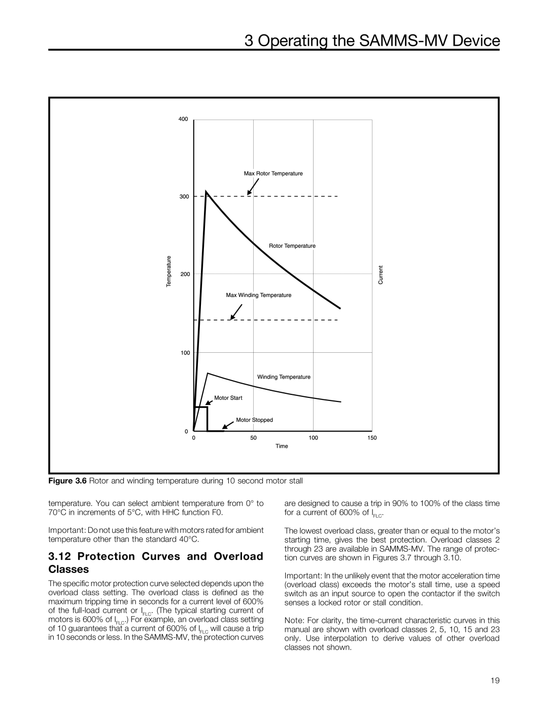
Figure 3.6 Rotor and winding temperature during 10 second motor stall
temperature. You can select ambient temperature from 0° to 70°C in increments of 5°C, with HHC function F0.
Important: Do not use this feature with motors rated for ambient temperature other than the standard 40°C.
3.12Protection Curves and Overload Classes
The specific motor protection curve selected depends upon the overload class setting. The overload class is defined as the maximum tripping time in seconds for a current level of 600% of the
are designed to cause a trip in 90% to 100% of the class time for a current of 600% of IFLC.
The lowest overload class, greater than or equal to the motor’s starting time, gives the best protection. Overload classes 2 through 23 are available in
Important: In the unlikely event that the motor acceleration time (overload class) exceeds the motor’s stall time, use a speed switch as an input source to open the contactor if the switch senses a locked rotor or stall condition.
Note: For clarity, the
19