4
1 Introduction

12345678910 11 12 13 1415 16

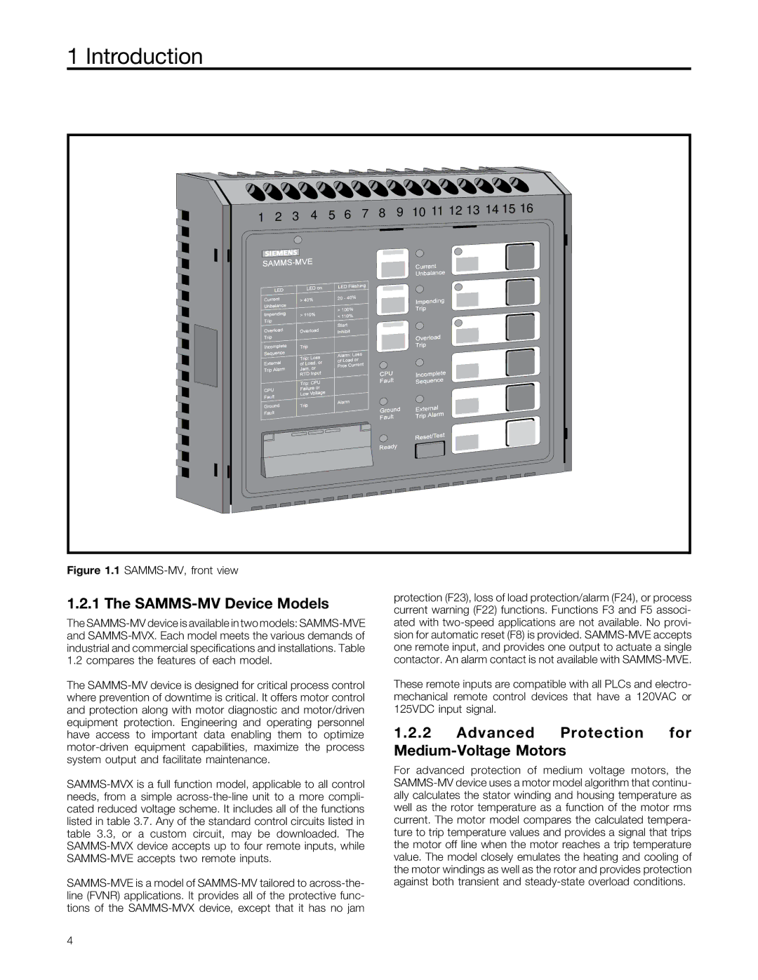
Figure 1.1 SAMMS-MV, front view
1.2.1 The SAMMS-MV Device Models
The SAMMS-MV device is available in two models: SAMMS-MVE
and SAMMS-MVX. Each model meets the various demands of
industrial and commercial specifications and installations. Table
1.2 compares the features of each model.
The SAMMS-MV device is designed for critical process control
where prevention of downtime is critical. It offers motor control
and protection along with motor diagnostic and motor/driven
equipment protection. Engineering and operating personnel
have access to important data enabling them to optimize
motor-driven equipment capabilities, maximize the process
system output and facilitate maintenance.
SAMMS-MVX is a full function model, applicable to all control
needs, from a simple across-the-line unit to a more compli-
cated reduced voltage scheme. It includes all of the functions
listed in table 3.7. Any of the standard control circuits listed in
table 3.3, or a custom circuit, may be downloaded. The
SAMMS-MVX device accepts up to four remote inputs, while
SAMMS-MVE accepts two remote inputs.
SAMMS-MVE is a model of SAMMS-MV tailored to across-the-
line (FVNR) applications. It provides all of the protective func-
tions of the SAMMS-MVX device, except that it has no jam
protection (F23), loss of load protection/alarm (F24), or process
current warning (F22) functions. Functions F3 and F5 associ-
ated with two-speed applications are not available. No provi-
sion for automatic reset (F8) is provided. SAMMS-MVE accepts
one remote input, and provides one output to actuate a single
contactor. An alarm contact is not available with SAMMS-MVE.
These remote inputs are compatible with all PLCs and electro-
mechanical remote control devices that have a 120VAC or
125VDC input signal.
1.2.2 Advanced Protection forMedium-Voltage Motors
For advanced protection of medium voltage motors, the
SAMMS-MV device uses a motor model algorithm that continu-
ally calculates the stator winding and housing temperature as
well as the rotor temperature as a function of the motor rms
current. The motor model compares the calculated tempera-
ture to trip temperature values and provides a signal that trips
the motor off line when the motor reaches a trip temperature
value. The model closely emulates the heating and cooling of
the motor windings as well as the rotor and provides protection
against both transient and steady-state overload conditions.