Manuals
/
Siemens
/
Marine Equipment
/
Outboard Motor
Siemens
SAMMS-MV
user manual
Samms-Mv
Models:
SAMMS-MV
1
1
52
52
Download
52 pages
64 Kb
1
2
3
4
5
6
7
8
Troubleshooting
Install
Custom Ladder Diagrams
Signal Words
Password
Ground Fault Detection
F13 Set Programmable Timer #1
Dimension
F8 Autoreset SAMMS-MVX Only
Phase Unbalance
Page 1
Image 1
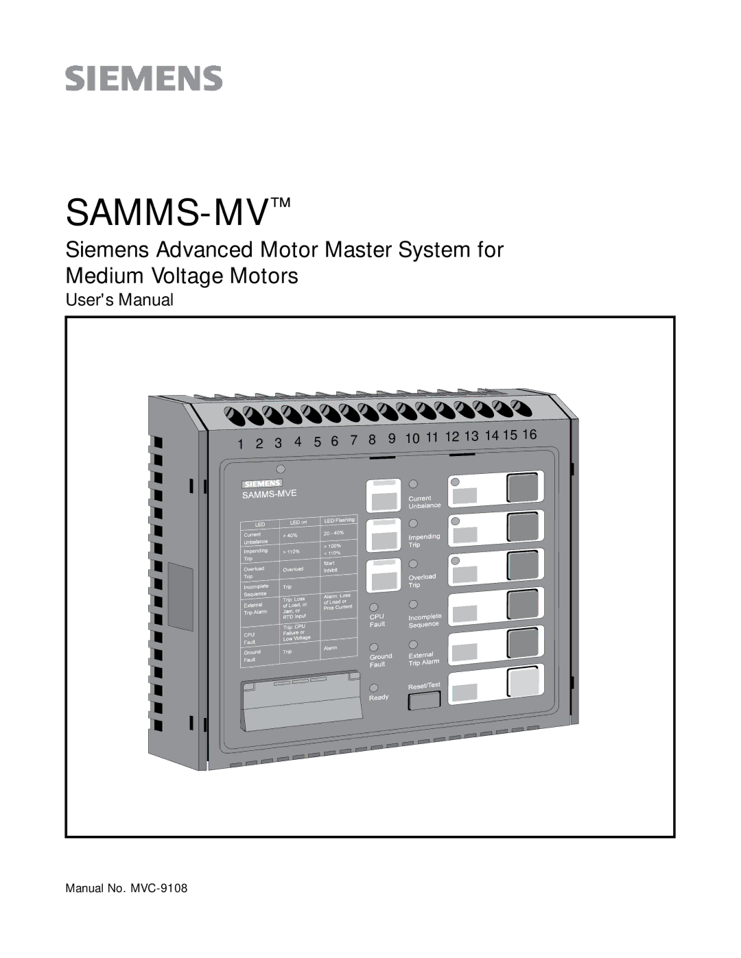
SAMMS-MV
™
Siemens Advanced Motor Master System for Medium Voltage Motors
User's Manual
1 2 3 4 5 6
7 8 9 10 11 12
13 14 15 16
Manual No.
MVC-9108
Page 1
Page 2
Page 1
Image 1
Page 1
Page 2
Contents
SAMMS-MV
Qualified Person
Contents
Field Service Operation
Signal Words
Qualified Person
About this Manual
Advanced Protection for Medium-Voltage Motors
SAMMS-MV Device Models
Overload Protection
Using the Standardized Control Panel
Programming Control Circuits
SAMMS-MV Model
Change settings requires password Yes Remote inputs One
Outputs One
Light bars
Installing the SAMMS-MV Device
Full voltage non-reversing connection diagram
Grounding the Device
SAMMS-MV device communications connections
Using the Reset/Test Push Button
Password Protection
Performing a Lamp Test
Performing an Overload Relay Test
Input Devices
Output Devices
Custom Ladder Diagrams
Ladder Diagrams Library of Standard Ladder Diagrams
SAMMS-MVX
Standard control circuits
PB1 PB2 PB3 PB4 PB5 PB6
Motor Ambient Temperature
Ridethrough Upon Loss of Power SAMMS-MVX Only
Incomplete Sequence
Intelligent Reduced-Voltage Starting SAMMS-MVX Only
ODP motor thermal signature
Protection Curves and Overload Classes
Seconds
Operating the SAMMS-MV
11 Motor protection graph
Phase Unbalance
Ultimate Trip Level and Service Factor
Dual Overload Protection SAMMS-MVX Only
Jam Protection SAMMS-MVX Only
Repetitive Starts
Ground Fault Detection
Start Inhibit
Cooling Time Constants
12 Multi-start scenario for an ODP motor
Using the Hand Held Communicator HHC
Autoreset After a Trip SAMMS-MVX Only
Emergency Restarting
Function Key
Function Number
5A CT primary current low speed if used Service factor
5A CT primary current if used Full load current for OLR No
Motor type Overload trip class class 2 through
Using the SAMMS-MV Device Func- tions
Using the Enter Key
UP and Down Keys
ON/OFF
Default Value
Select ground fault pick-up current
Means warning
Select jam pickup current 120-400% Iflc F24 Loss of Load
13 Entering and changing passwords
F0 Ambient Temperature
Program Mode/Passwords
SAMMS-MV Functions
F1 Control Circuit Number and Incomplete Se- quence Status
F3 Size for Overload Relay #2 SAMMS-MVX Only
Overload Setting Step Default Relay Size Range
F4 Full-Load Current for Overload Relay #1
18 to 72A
F6A Motor Type
F6 Service Factor
F7 Overload Trip Class
F7A Cold Stall Time
F9 Phase Unbalance Protection
F8 Autoreset SAMMS-MVX Only
F10 Display Time to Restart
F11 Emergency Restarting
F12A Ground Fault Pickup Current
F12 Ground Fault Protection or Warning
Size Pickup Current Default H3A-H3C 7A-I FLC 10A 20A
F13 Set Programmable Timer #1
F16 Trip Current
F21 Reset Motor Data
F17 Current Unbalance
F18 Display Total Elapsed Run Time of the Motor
F22 Process Current Warning Level SAMMS-MVX Only
F25 Percentage of Motor Winding Temperature
F23 Jam Protection SAMMS-MVX Only
F23A Jam Pickup Current SAMMS-MVX Only
F27 Address
F26 Baud Rate
Troubleshooting
Error Condition
Troubleshooting Guide Error Condition
Appendix a Technical Specifications
Over load Spec ificat ions
Stat ist ica l Data
Dimensions
Catalog Number SAM6
Switch # Function Position
375
Siemens Energy Automation, Inc
Top
Page
Image
Contents