3700
Table of Contents
Glossary of Terms
Work Area
General Safety Rules
Personal Safety
Tool Use
Basic Operation and Set Up
Table Saw Specific Safety Rules
Tool Care
Plunge Cutting
Rip Cutting
Cross Cutting
Dragged into the blade during a kickback
Non-Through Cutting Dado, Rabbet, Resawing
Shop Safety Rules
Accessory Power Outlet
Kickback
Sander Safety
Router Table Safety
Throwing fragments
Jigsaw Safety
Extension Cords
Double Insulated Tools
Grounded Tools
Replace damaged cords immediately
Page
« Conservez CES Instructions »
Utilisation des accessoires X-Shop avec
Table des matières
Informations relatives à la sécurité
Lexique
Sécurité de l’utilisateur
Consignes générales de sécurité
Zone de travail
Utilisation de l’outil
Utilisation et réglages élémentaires
Consignes de sécurité pour les scies de table
Protection de l’outil
Prenez Soin DE VOS Outils ET ENTRETENEZ-LES Bien
Sciage en travers
Refente
Sciage en plongée
Consignes de sécurité pour X-Shop
Coupes non débouchantes Rainures, feuillures, dédoublement
Coincera le matériau et risquera de causer un rebond
Consignes de sécurité pour une table à toupie
De causer une perte de contrôle
Consignes de sécurité Pour une scie à chantourner
Cordons de rallonge
Outils à double isolation
Outils mis à la terre
En la matière
Étiquettes d’avertissement
Pour Continuation DU FRANÇAIS, REPORTEZ-VOUS À LA
Índice
Guarde Estas Instrucciones
Glosario de términos
Seguridad personal
Normas generales de seguridad
Area de trabajo
Utilización de la herramienta
Evite LAS Areas DE Gases
Cuidado de la herramienta
Funcionamiento y preparación básicos
Mantenga LAS Herramientas CON Cuidado
Corte transversal
Corte al hilo
Corte por penetración
Corte no pasante De mortaja, rebajo o reaserrado
Sea consciente de la proximidad de la mano y los dedos a la
Instrucciones de seguridad para mesas de fresadora
Podría causar una pérdida de control
Instrucciones de seguridad Para sierras caladoras
Cordones de extensión
Herramientas con aislamiento doble
Herramientas conectadas a tierra
Conserve Estas Instrucciones
Etiquetas de advertencia
VER Continuación DEL Español EN LA Página
Unpacking Checking Contents
Pièces détachées dans le carton
Piezas sueltas contenidas en la caja de cartón
Cabinet P Arts
Assembly Kits
Small parts
Kits de montage Juegos de ensamblajes
Ensemble du coffret Ensamblaje del armario
Hardware Kit Jigsaw Insert
Hardware Kit Sander Insert
Hardware Kit Blank Insert
Tope-guía de lijadora Tope-guía de fresadora
Guide de ponceuse Guide de toupie
Plaquette amovible pour ponceuse
Juego de ensamblaje de sierra
Tools Needed For Assembly
Hardware Kit Router Insert
Plaquette amovible pour toupie
Outils nécessaires à l’assemblage
Herramientas necesarias para el ensamblaje
Juego de herrajes del accesorio
Assembly
Assembling Cabinet
Assemblage du coffret
AssemblageEnsamblaje
Ensamblaje del armario
C16 C19 C17
Assemblage du coffret suite
Ensamblaje del armario continuación
Attaching Wings
Attaching Front Rails
Ensamblaje de las alas
Montage des ailes
Montage du rail avant
Colocación del riel delantero
Attaching Handle To Rip Fence
Attaching Digital Display
T18
Colocación del mango en El tope-guía para cortar al hilo
Montage de l’écran ’affichage numérique
Attach handle to wheel using bolt as shown in figure
Attaching Handle to Elevation Wheel
Colocación del tope-guía Para cortar al hilo
Montage du guide de refente
Réglage de hauteur
Colocación del mango en el rueda de Elevacion
Attaching Blade Guard
Colocación del protector de la hoja
Montage du protège-lame
Perno hexagonal de 1/4-20 x 2 pulg
Attaching Blank Insert
Wings and blank insert must be installed
Order to use the table saw. Wings and blank
Montage de l’ébauche de plaquette amovible
Attaching Router Insert
Outil non joint / Herramienta no incluida
Art Description
Montage de la plaquette Amovible pour toupie
’emploi qui accompagne la toupie
Instrucciones que vino con la fresadora
Attaching Sander Insert
Montage de la plaquette amovible pour ponceuse
De instrucciones que vino con la lijadora
Attaching Jigsaw Insert
Montage de la plaquette amovible Pour scie à chantourner
Colocación del accesorio De inserción de sierra caladora
Getting To Know Your Shop
Outils X-Shop
Taller convertible X-Shop
RIP Fence Storage
Accessory Tool Inserts
Wrench Storage
Cord Wrap
Rangement DU Guide DE Coupe Angulaire
Rangement DES Clés
Rangement DU Guide DE Refente
Rangement DU Cordon
Sander not included
Miter Gauge
Router not included
Jigsaw not included
Accesorios DE Inserción Para Herramientas
Plaquettes Amovibles Pour Accessoires
Guide DE Coupe Angulaire
Calibre DE Ingletes
Adjusting Positive Stop AT 90 Degrees
Table Saw Adjustments
Adjusting 90 and 45 Degree Positive Stops
Adjusting Positive Stop AT 45 Degrees
Ajuste de los topes positivos 90 y 45 grados
Réglage des butées positives 90 et 45 degrés
Control de inclinación de la hoja
Para el calibre de ingletes
Adjusting Blade Parallel To Miter Gauge Slots
Changing The Blade
De changer la lame
Remplacement de la lame
Cambio de la hoja
De cambiar las hojas
Shop Tools Adjustments
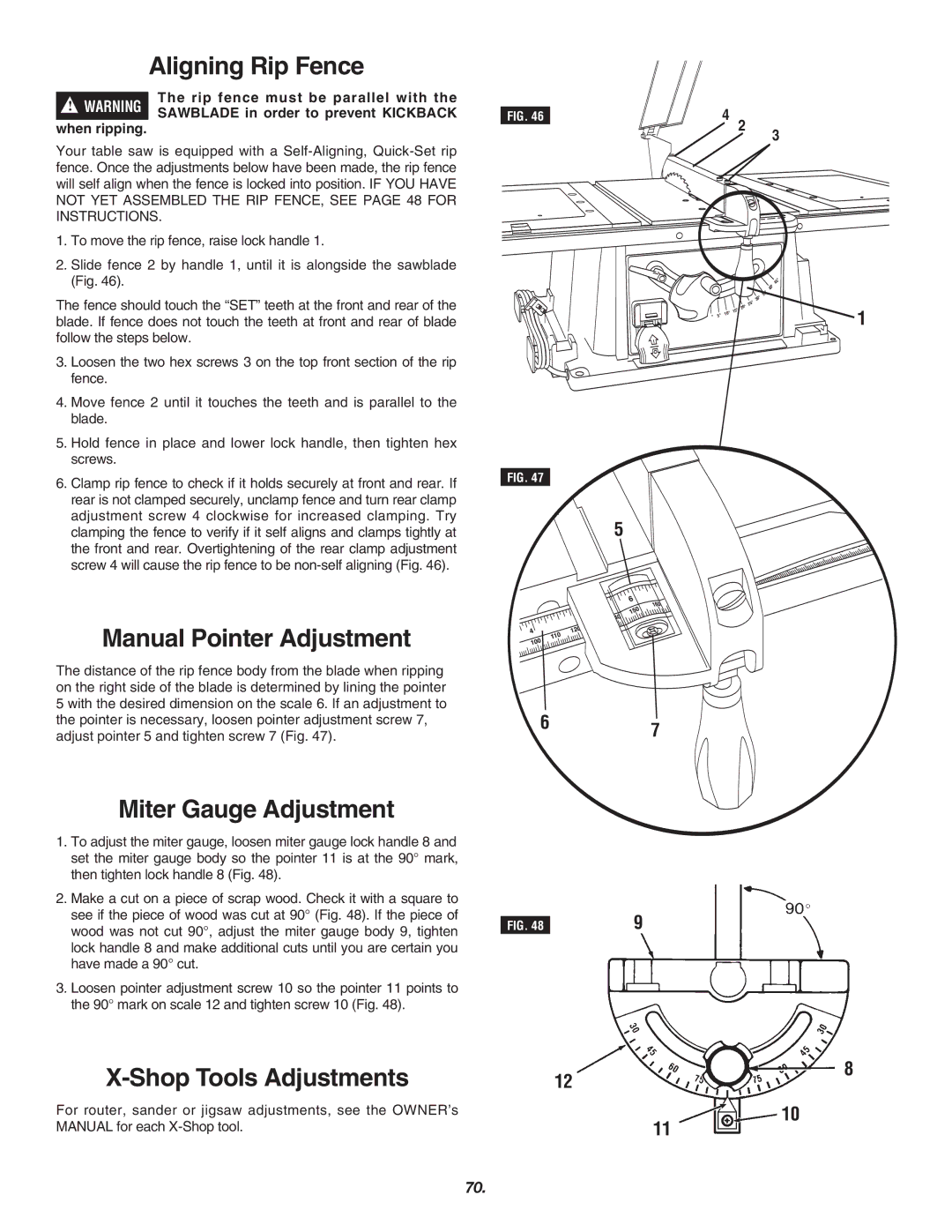
Manual Pointer Adjustment
Miter Gauge Adjustment
Aligning Rip Fence
Alineación del tope-guía Para cortar al hilo
Alignement du guide de refente
Réglage manuel de l’aiguille
Ajuste manual del indicador
Using The Miter Gauge
Table Saw Power Switch
Using the Miter Gauge with T Bar
Basic Table Saw Operation
Utilización básica De la sierra de mesa
Push Stick and Push Block
Work Helpers
Auxiliary Fence
Palo de empujar y bloque de empujar
Accessoires de sciage
Ayudantes de trabajo
Guide auxiliaire
Using the Rip Fence
Utilización del tope-guía Para cortar al hilo
Utilisation du guide de refente
Pour votre propre sécurité
Operating the Digital Display
Error Messages
Ripping
Corte al hilo
Mensajes DE Error
Refente
Messages D’ERREUR
Bevel Ripping
Crosscutting
Corte al hilo en bisel
Refente biseautée
Coupe transversale
Corte transversal
Bevel Crosscutting
Repetitive Cutting
Miter Cutting
Compound Miter Cutting
Coupe transversale biseautée
Coupes à répétition
Coupe angulaire
Coupe angulaire combinée
Making a Featherboard
Non Thru-Sawing
Rabbeting
Aserrado no pasante
Sciage non débouchant
Feuillure
Elaboración de una tabla De canto biselado
Resawing
Dado Cutting
Special Cutting Techniques
Coupe à dédoublement
Rainure
Corte de mortajas
Techniques de coupe spéciales
Off position
Using X-Shop Accessories With Inserts
Never leave the power tool unattended while it is
Running or before it comes to a complete stop
Avant qu’il ne soit complètement à l’arrêt
De apagado
To Adjust the Router BIT Height
To Adjust the Fence Opening for Router BIT Clearance FIG
To Adjust the Depth of CUT FIG
Installing the Router BIT Positioning the Guard
Utilisation de la toupie X-Shop
Utilización de la fresadora X-Shop
Using the Feather Board On the Fence Figure
Routing Using the Feather Board
Using the Feather Board on Table TOP
Fence Location and Workpiece Feed
Sobre EL Tablero DE LA Mesa
SUR LE Dessus DE LA Table
SUR LE Guide Figure
Sobre EL TOPE-GUÍA Figura
Routing Using the Fence
Jointing Full Edge Cutting
Junteo Corte DE Bordes Completos
Installez une mèche droite dans la toupie
Instale una broca recta en la fresadora
Edge Cutting with NON-PILOTED Router Bits
Edge Cutting with Piloted Router Bits
SIN Punta Piloto
Installez la mèche désirée dans la toupie
NON Pilotées
Toupie Pilotées
GROOVING, FLUTING, and Veining
Création DE RAINURES, D’ENTAILLES ET DE Veinures
RANURADO, Estriado Y Acanalado
Shop Sander Operation
Pinching or entrapment of fingers
Utilisation de la ponceuse X-Shop
Utilización de la lijadora X-Shop
Shop Jigsaw Operation
Utilización de la sierra caladora X-Shop
Maintaining Your Shop
Maintenance
Lubrication
Lubrification
Mantenimiento de la sierra De mesa X-Shop
Mantenimiento
Lubricación
Instructions that accompany accessories
Recommended Accessories
Use only recommended accessories. Follow
Use of improper accessories may cause hazards
Accesorios recomendados
Trouble Shooting
Guide de diagnostic
Localización y reparación De averías
Averia LA Sierra no Arranca
110
RemarquesNotas
Limited Warranty of Skil Benchtop Tools