Wiring (continued )
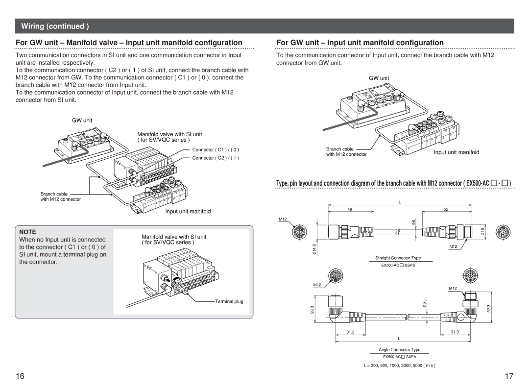
For GW unit – Manifold valve – Input unit manifold configuration
Two communication connectors in SI unit and one communication connector in Input unit are installed respectively.
To the communication connector ( C2 ) or ( 1 ) of SI unit, connect the branch cable with M12 connector from GW. To the communication connector ( C1 ) or ( 0 ), connect the branch cable with M12 connector from Input unit.
To the communication connector of Input unit, connect the branch cable with M12 connector from SI unit.
GW unit
Manifold valve with SI unit ( for SV/VQC series )
Connector ( C1 ) / ( 0 )
Connector ( C2 ) / ( 1 )
Branch cable
with M12 connector
Input unit manifold
NOTE
Manifold valve with SI unit
When no Input unit is connected( for SV/VQC series ) to the connector ( C1 ) or ( 0 ) of
SI unit, mount a terminal plug on the connector.
![]() Terminal plug
Terminal plug
For GW unit – Input unit manifold configuration
To the communication connector of Input unit, connect the branch cable with M12 connector from GW unit.
GW unit
Branch cable | Input unit manifold | |
with M12 connector | ||
|
Type, pin layout and connection diagram of the branch cable with M12 connector ( ![]() -
- ![]() )
)
| L |
48 | 52 |
M12 | 6 |
| 16 |
14.9 | M12 |
| |
| Straight Connector Type |
| |
M12 | M12 |
| |
| 6 |
28.3 | 32.3 |
31.3 | 31.3 |
| L |
Angle Connector Type
![]() -SAPA
-SAPA
L = 300, 500, 1000, 3000, 5000 ( mm )
16 | 17 |