Display/Switch Setting
 Display
LAN
PWR ![]()
![]()
![]()
![]() LINK
LINK
![]()
![]() 100
100
MS ![]()
NS
GATEWAY UNIT
EX500 SERIES
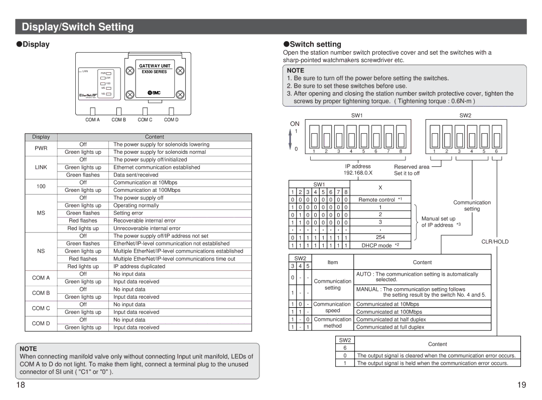
 Switch setting
Open the station number switch protective cover and set the switches with a
NOTE
1.Be sure to turn off the power before setting the switches.
2.Be sure to set these switches before use.
3.After opening and closing the station number switch protective cover, tighten the screws by proper tightening torque. ( Tightening torque : 0.6N m )
SW1SW2
| COM A | COM B | COM C | COM D | |
|
|
|
|
| |
Display |
|
| Content |
| |
PWR | Off | The power supply for solenoids lowering | |||
|
|
|
| ||
Green lights up | The power supply for solenoids normal | ||||
| |||||
|
|
| |||
| Off | The power supply off/initialized | |||
|
|
| |||
LINK | Green lights up | Ethernet communication established | |||
|
|
|
| ||
| Green flashes | Data sent/received |
| ||
|
|
| |||
100 | Off | Communication at 10Mbps | |||
|
|
|
| ||
Green lights up | Communication at 100Mbps | ||||
| |||||
|
|
|
| ||
| Off | The power supply off |
| ||
|
|
|
| ||
| Green lights up | Operating normally |
| ||
|
|
|
| ||
MS | Green flashes | Setting error |
| ||
|
|
| |||
| Red flashes | Recoverable internal error | |||
|
|
| |||
| Red lights up | Unrecoverable internal error | |||
|
|
| |||
| Off | The power supply off/IP address not set | |||
|
|
| |||
| Green flashes | ||||
|
|
| |||
NS | Green lights up | Multiple | |||
|
|
| |||
| Red flashes | Multiple | |||
|
|
| |||
| Red lights up | IP address duplicated | |||
|
|
|
| ||
COM A | Off | No input data |
| ||
|
|
|
| ||
Green lights up | Input data received |
| |||
|
| ||||
|
|
|
| ||
COM B | Off | No input data |
| ||
|
|
|
| ||
Green lights up | Input data received |
| |||
|
| ||||
|
|
|
| ||
COM C | Off | No input data |
| ||
|
|
|
| ||
Green lights up | Input data received |
| |||
|
| ||||
|
|
|
| ||
COM D | Off | No input data |
| ||
|
|
|
| ||
Green lights up | Input data received |
| |||
|
| ||||
NOTE
When connecting manifold valve only without connecting Input unit manifold, LEDs of COM A to D do not light. To make them light, connect a terminal plug to the unused connector of SI unit ( "C1" or "0" ).
ON |
|
|
|
|
|
|
|
|
|
|
|
|
|
|
|
|
|
|
|
|
|
|
|
|
|
|
|
|
|
|
|
|
|
|
|
|
|
|
|
|
|
|
|
|
|
|
|
|
|
|
|
|
|
|
|
|
|
|
|
|
|
|
| ||
| 1 |
|
|
|
|
|
|
|
|
|
|
|
|
|
|
|
|
|
|
|
|
|
|
|
|
|
|
|
|
|
|
|
|
|
|
|
|
|
|
|
|
|
|
|
|
|
|
|
|
|
|
|
|
|
|
|
|
|
|
|
|
|
|
| |
| 0 |
|
|
|
|
|
|
|
|
|
|
|
|
|
|
|
|
|
|
|
|
|
|
|
|
|
|
|
|
|
|
|
|
|
|
|
|
|
|
|
|
|
|
|
|
|
|
|
|
|
|
|
|
|
|
|
|
|
|
|
|
|
|
| |
|
|
|
|
|
|
|
|
|
|
|
|
|
|
|
|
|
|
|
|
|
|
|
|
|
|
|
|
|
|
|
|
|
|
|
|
|
|
|
|
|
|
|
|
|
|
|
|
|
|
|
|
|
|
|
|
|
|
|
|
|
|
|
| ||
|
| 1 |
|
|
| 2 |
|
| 3 | 4 |
| 5 |
|
|
| 6 | 7 |
| 8 |
|
|
|
| 1 |
| 2 |
|
| 3 | 4 |
|
|
| 5 |
| 6 |
|
|
| ||||||||||||||||||||||||||
|
|
|
|
|
|
|
|
|
|
|
|
|
|
|
|
|
|
|
|
|
|
|
|
|
|
|
| ||||||||||||||||||||||||||||||||||||||
|
|
|
|
|
|
|
|
|
|
|
|
|
|
|
|
|
|
|
|
|
|
|
|
|
|
|
|
|
|
|
|
|
|
|
|
|
|
|
|
|
|
|
|
|
|
|
|
|
|
|
|
|
|
| |||||||||||
|
|
|
|
|
|
|
|
|
|
|
|
|
|
|
|
|
|
|
|
|
|
|
|
|
|
|
|
|
|
|
|
|
|
|
|
|
|
|
|
|
|
|
|
|
|
|
|
|
|
|
|
|
|
|
|
|
|
|
|
|
|
|
|
|
|
|
|
|
|
|
|
|
|
|
|
|
|
|
|
|
|
|
|
|
|
|
|
|
|
|
|
|
|
|
|
|
|
|
|
|
|
|
|
|
|
|
|
|
|
|
|
|
|
|
|
|
|
|
|
|
|
|
|
|
|
|
|
|
|
|
|
|
|
|
|
|
|
|
|
|
|
|
|
|
|
|
| IP address |
|
|
|
|
|
|
| Reserved area |
|
|
|
|
|
|
|
|
|
|
|
|
|
|
|
|
|
|
|
|
|
|
|
|
|
| |||||||||||||||
|
|
|
|
|
|
|
|
|
|
|
|
|
|
|
|
|
|
|
|
|
|
|
|
|
|
|
|
|
|
|
|
|
|
|
|
|
|
|
|
|
|
|
|
|
|
|
|
| |||||||||||||||||
|
|
|
|
|
|
|
|
|
|
|
|
|
|
| 192.168.0.X |
|
|
|
|
|
|
| Set it to off |
|
|
|
|
|
|
|
|
|
|
|
|
|
|
|
|
|
|
|
|
|
|
|
|
|
| ||||||||||||||||
|
|
|
|
|
|
|
|
|
|
|
|
|
|
|
|
|
|
|
|
|
|
|
|
|
|
|
|
|
|
|
|
|
|
|
|
|
|
|
|
|
|
|
|
|
|
|
|
|
|
|
|
|
|
|
|
|
|
|
|
| |||||
|
|
|
|
| SW1 |
|
|
|
|
|
|
|
|
|
|
|
|
|
| X |
|
|
|
|
|
|
|
|
|
|
|
|
|
|
|
|
|
|
|
|
|
|
|
|
|
|
|
|
|
|
|
|
| ||||||||||||
1 |
| 2 | 3 | 4 |
| 5 |
| 6 | 7 | 8 |
|
|
|
|
|
|
|
|
|
|
|
|
|
|
|
|
|
|
|
|
|
|
|
|
|
|
|
|
|
|
|
|
|
|
|
|
|
|
|
|
|
| |||||||||||||
|
|
|
|
|
|
|
|
|
|
|
|
|
|
|
|
|
|
|
|
|
|
|
|
|
|
|
|
|
|
|
|
|
|
|
|
|
|
|
|
|
|
|
|
|
|
|
|
|
|
| |||||||||||||||
0 |
| 0 | 0 | 0 |
| 0 |
| 0 | 0 | 0 |
|
|
| Remote control *1 |
|
|
|
|
|
|
|
|
|
|
|
|
|
|
|
|
|
|
|
|
|
|
|
|
|
|
| ||||||||||||||||||||||||
|
|
|
|
|
|
|
|
|
|
|
| Communication |
|
|
|
|
|
| |||||||||||||||||||||||||||||||||||||||||||||||
1 |
| 0 | 0 | 0 |
| 0 |
| 0 | 0 | 0 |
|
|
|
|
|
|
|
|
| 1 |
|
|
|
|
|
|
|
|
|
|
|
|
|
|
|
|
|
|
|
|
|
|
|
| |||||||||||||||||||||
|
|
|
|
|
|
|
|
|
|
|
|
|
|
|
|
|
|
|
|
|
|
|
|
|
|
|
|
|
|
|
| setting |
|
|
|
|
|
|
|
| |||||||||||||||||||||||||
0 |
| 1 | 0 | 0 |
| 0 |
| 0 | 0 | 0 |
|
|
|
|
|
|
|
|
| 2 |
|
|
|
|
|
|
|
| Manual set up |
|
|
|
|
|
|
|
|
|
|
|
|
|
|
|
| ||||||||||||||||||||
|
|
|
|
|
|
|
|
|
|
|
|
|
|
|
|
|
|
|
|
|
|
|
|
|
|
|
|
|
|
|
|
|
| ||||||||||||||||||||||||||||||||
1 |
| 1 | 0 | 0 |
| 0 |
| 0 | 0 | 0 |
|
|
|
|
|
|
|
|
| 3 |
|
|
|
|
|
|
|
|
|
|
|
|
|
|
|
|
|
|
|
|
|
|
|
| |||||||||||||||||||||
|
|
|
|
|
|
|
|
|
|
|
|
|
|
|
|
|
|
|
| of IP address | *3 |
|
|
|
|
|
|
|
|
|
|
|
|
|
|
|
| ||||||||||||||||||||||||||||
|
|
|
|
|
|
|
|
|
|
|
|
|
|
|
|
|
|
|
|
|
|
|
|
|
|
|
|
|
|
|
|
|
|
|
|
|
|
|
|
|
|
|
|
|
|
|
|
|
|
|
|
|
| ||||||||||||
|
|
|
|
|
|
|
|
|
|
|
|
|
|
|
|
|
|
|
|
|
|
|
|
|
|
|
|
|
|
|
|
|
|
|
|
|
|
|
|
|
|
|
|
|
|
|
|
|
|
|
|
|
|
|
| ||||||||||
0 |
| 1 | 1 | 1 |
| 1 |
| 1 | 1 | 1 |
|
|
|
|
|
|
|
| 254 |
|
|
|
|
|
|
|
|
|
|
|
|
|
|
|
|
|
|
|
|
|
|
|
|
|
|
|
|
|
|
|
|
|
|
| |||||||||||
|
|
|
|
|
|
|
|
|
|
|
|
|
|
|
|
|
|
|
|
|
|
|
|
|
|
|
|
|
|
|
|
|
|
|
| CLR/HOLD | |||||||||||||||||||||||||||||
1 |
| 1 | 1 | 1 |
| 1 |
| 1 | 1 | 1 |
|
|
|
| DHCP mode *2 |
|
|
|
|
|
|
|
|
|
|
|
|
|
|
|
|
|
|
|
| ||||||||||||||||||||||||||||||
|
|
|
|
|
|
|
|
|
|
|
|
|
|
|
|
|
|
|
|
|
|
|
|
|
|
|
|
|
|
|
|
|
| ||||||||||||||||||||||||||||||||
|
|
|
|
|
|
|
|
|
|
|
|
|
|
|
|
|
|
|
|
|
|
|
|
|
|
|
|
|
|
| |||||||||||||||||||||||||||||||||||
|
|
|
|
|
|
|
|
|
|
|
|
|
|
|
|
|
|
|
|
|
|
|
|
|
|
|
|
|
|
|
|
|
|
|
|
|
|
|
|
|
|
|
|
|
|
|
|
|
|
|
|
|
|
|
|
|
|
|
|
|
|
|
|
|
|
| SW2 |
|
|
|
|
|
|
| Item |
|
|
|
|
|
|
|
|
|
|
|
|
|
|
|
|
|
|
|
|
|
|
| Content |
|
|
|
|
|
|
|
|
|
|
|
|
|
|
|
|
|
|
|
|
|
|
|
|
|
| ||||||
3 |
| 4 | 5 |
|
|
|
|
|
|
|
|
|
|
|
|
|
|
|
|
|
|
|
|
|
|
|
|
|
|
|
|
|
|
|
|
|
|
|
|
|
|
|
|
|
|
|
|
|
|
|
|
|
|
|
|
|
|
| |||||||
|
|
|
|
|
|
|
|
|
|
|
|
|
|
|
|
|
|
|
|
|
|
|
|
|
|
|
|
|
|
|
|
|
|
|
|
|
|
|
|
|
|
|
|
|
|
|
|
|
|
|
|
|
|
|
|
|
|
|
|
|
|
| |||
0 |
| - | - |
|
|
|
|
|
|
|
|
|
|
|
|
|
|
|
| AUTO : The communication setting is automatically |
|
|
|
|
|
|
|
| |||||||||||||||||||||||||||||||||||||
|
| Communication |
|
|
|
|
|
|
| selected. |
|
|
|
|
|
|
|
|
|
|
|
|
|
|
|
|
|
|
|
|
|
|
|
|
|
| |||||||||||||||||||||||||||||
|
|
|
|
|
|
|
|
|
|
|
|
|
|
|
|
|
|
|
|
|
|
|
|
|
|
|
|
|
|
|
|
|
|
|
|
|
| ||||||||||||||||||||||||||||
|
|
|
|
|
|
|
|
|
|
|
|
|
|
|
|
|
|
|
|
|
|
|
|
|
|
|
|
|
|
|
|
|
|
|
|
|
|
|
|
|
|
|
|
|
|
|
|
|
|
|
| ||||||||||||||
1 |
| - | - |
|
|
|
|
| setting |
|
|
|
|
| MANUAL : The communication setting follows |
|
|
|
|
|
|
|
| ||||||||||||||||||||||||||||||||||||||||||
|
|
|
|
|
|
|
|
|
|
|
|
|
|
|
|
|
|
|
|
|
|
|
|
| |||||||||||||||||||||||||||||||||||||||||
|
|
|
|
|
|
|
|
|
|
|
|
|
|
|
|
|
|
|
|
|
|
|
|
|
| the setting result by the switch No. 4 and 5. |
|
|
|
|
|
| |||||||||||||||||||||||||||||||||
|
|
|
|
|
|
|
|
|
|
|
|
|
|
|
|
|
|
|
|
|
|
|
|
|
|
|
|
|
|
|
|
|
|
| |||||||||||||||||||||||||||||||
|
|
|
|
|
|
|
|
|
|
|
|
|
|
|
|
|
|
|
|
|
|
|
|
|
|
|
|
|
|
|
|
|
|
| |||||||||||||||||||||||||||||||
1 |
| 0 | - |
| Communication |
| Communicated at 10Mbps |
|
|
|
|
|
|
|
|
|
|
|
|
|
|
|
|
|
|
|
|
|
|
|
|
|
| ||||||||||||||||||||||||||||||||
1 |
| 1 | - |
|
|
|
|
| speed |
|
|
|
|
| Communicated at 100Mbps |
|
|
|
|
|
|
|
|
|
|
|
|
|
|
|
|
|
|
|
|
|
|
|
|
|
| ||||||||||||||||||||||||
1 |
| - | 0 |
| Communication |
| Communicated at half duplex |
|
|
|
|
|
|
|
|
|
|
|
|
|
|
|
|
|
|
|
|
|
|
|
|
|
| ||||||||||||||||||||||||||||||||
1 |
| - | 1 |
|
|
|
|
| method |
|
|
|
|
| Communicated at full duplex |
|
|
|
|
|
|
|
|
|
|
|
|
|
|
|
|
|
|
|
|
|
|
|
|
|
| ||||||||||||||||||||||||
|
|
|
|
|
|
|
|
|
|
|
|
|
|
|
|
|
|
|
|
|
|
|
|
|
|
|
|
|
|
|
|
|
|
|
|
|
|
|
|
|
|
|
|
|
|
|
|
|
|
|
|
|
|
|
|
|
|
|
|
|
|
|
|
|
|
|
|
|
|
|
|
|
|
|
|
|
|
|
| SW2 |
|
|
|
|
|
|
|
|
|
|
|
|
|
|
|
|
|
|
| Content |
|
|
|
|
|
|
|
|
|
|
|
|
|
|
|
|
|
| |||||||||||||
|
|
|
|
|
|
|
|
|
|
|
|
|
|
| 6 |
|
|
|
|
|
|
|
|
|
|
|
|
|
|
|
|
|
|
|
|
|
|
|
|
|
|
|
|
|
|
|
|
|
|
|
|
|
|
|
| ||||||||||
|
|
|
|
|
|
|
|
|
|
|
|
|
|
|
|
|
|
|
|
|
|
|
|
|
|
|
|
|
|
|
|
|
|
|
|
|
|
|
|
|
|
|
|
|
|
|
|
|
|
|
|
|
|
|
|
|
|
|
|
|
|
|
| ||
0The output signal is cleared when the communication error occurs.
1The output signal is held when the communication error occurs.
18 | 19 |