Display/Switch Setting (continued )
*1 : Remote control (SW1 all dip-switches off)
SMC's EX500 GW Unit will respond to the following Rockwell Automation BOOTP/DHCP Server commands.
Enable DHCP
Selecting this function will enable the EX500 GW Unit to retrieve its boot information from the BOOTP/DHCP Server. If DHCP is enabled the EX500 GW Unit will retrieve its boot information during the next power up.
Disable BOOTP/DHCP
Selecting this function will disable the EX500 to retrieve its boot information from the BOOTP/DHCP Server, and causes the EX500 to retain its current configuration during the next power up.
*2 : DHCP Mode (SW1 all dip-switches on)
The IP address is acquired via DHCP Server. The IP address is not saved and lost if the power to the EX500 unit is cycled.
*3 : Hardware Addressing
The IP address range is
Default settings
At the time of factory shipment, the product is in "Remote Control Mode" and set to "Enable DHCP".
NOTE
If the stored IP address of an EX500 is not known, please go to the "DHCP Mode" section.
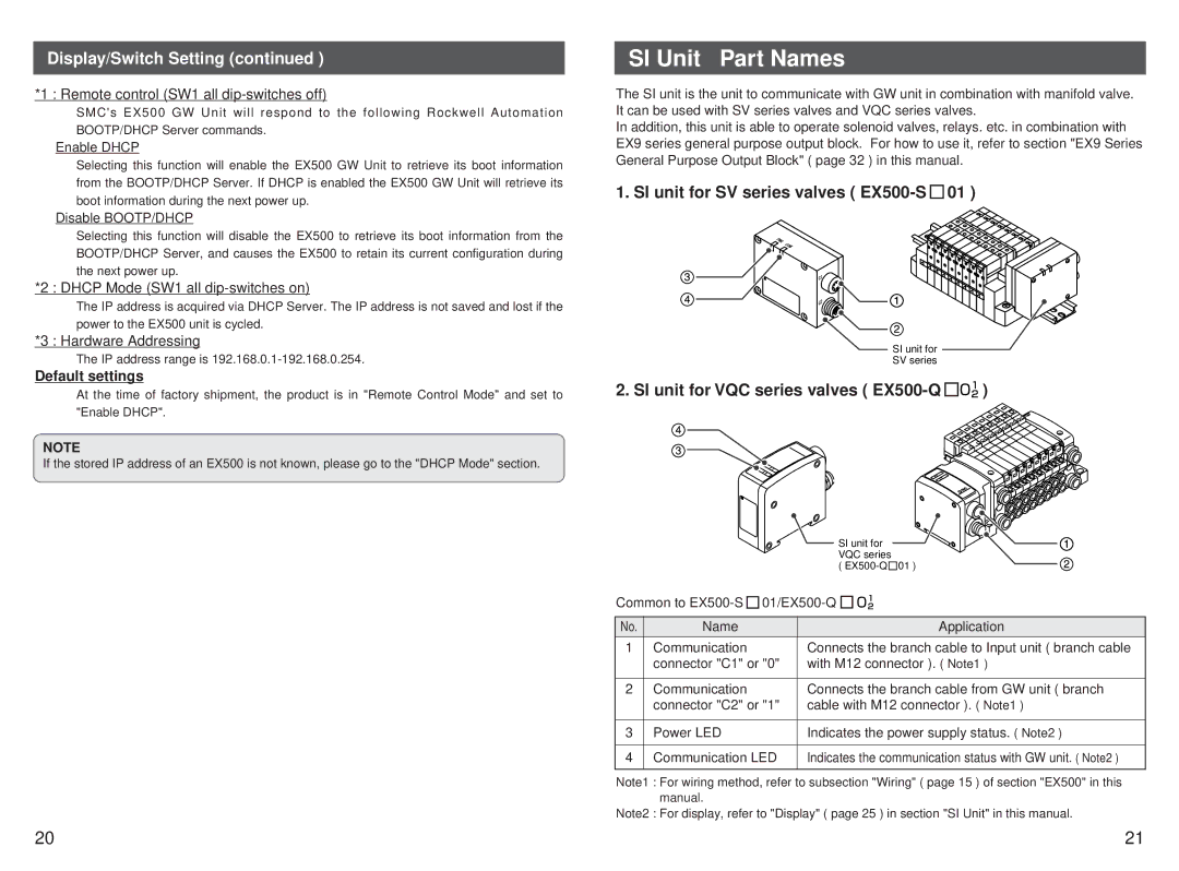
SI Unit Part Names
The SI unit is the unit to communicate with GW unit in combination with manifold valve. It can be used with SV series valves and VQC series valves.
In addition, this unit is able to operate solenoid valves, relays. etc. in combination with EX9 series general purpose output block. For how to use it, refer to section "EX9 Series General Purpose Output Block" ( page 32 ) in this manual.
1. SI unit for SV series valves ( EX500-S  01 )
01 )
SI unit for
SV series
2. SI unit for VQC series valves ( EX500-Q 

 )
)
SI unit for VQC series
( ![]() 01
01
Common to ![]()
![]()
![]()
![]()
No. | Name | Application |
1 | Communication | Connects the branch cable to Input unit ( branch cable |
| connector "C1" or "0" | with M12 connector ). ( Note1 ) |
|
|
|
2 | Communication | Connects the branch cable from GW unit ( branch |
| connector "C2" or "1" | cable with M12 connector ). ( Note1 ) |
|
|
|
3 | Power LED | Indicates the power supply status. ( Note2 ) |
|
|
|
4 | Communication LED | Indicates the communication status with GW unit. ( Note2 ) |
|
|
|
Note1 : For wiring method, refer to subsection "Wiring" ( page 15 ) of section "EX500" in this manual.
Note2 : For display, refer to "Display" ( page 25 ) in section "SI Unit" in this manual.
20 | 21 |