Dimensions ( unit : mm )
1. SI unit for SV series valves ( EX500-S  01 )
01 )
79.4
28.6
68.5
54.5 | 39 |
15.5![]()
2.SI unit for VQC series valves ( EX500-Q  01 )
01 )
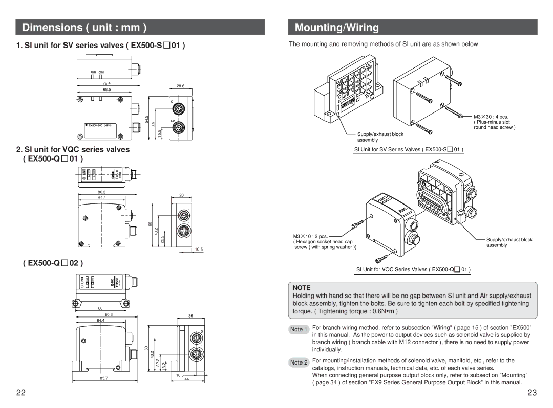
Mounting/Wiring
The mounting and removing methods of SI unit are as shown below.
M3![]() 30 : 4 pcs. (
30 : 4 pcs. (
Supply/exhaust block assembly
SI Unit for SV Series Valves ( ![]()
| PWR |
|
| COM | ||
|
|
|
|
|
|
|
80.3
64.4
28
0
60 | 1 |
| |
| 43.2 |
| 22.2 |
10.5
( EX500-Q  02 )
02 )
SI UNIT | PWR | COM | EX500 | series |
|
|
| 66 |
|
|
|
|
| 80.3 |
|
| 36 |
|
| 64.4 |
|
| |
|
|
|
|
| |
|
|
|
|
| 0 |
|
|
|
| 60 | 1 |
|
|
|
|
| |
|
|
|
| 43.2 |
|
|
|
|
| 22.2 | 13.2 |
|
| 85.7 |
|
| 10.5 |
|
|
|
| 44 |
M3 10 : 2 pcs. | Supply/exhaust block | |
( Hexagon socket head cap | ||
assembly | ||
screw ( with spring washer )) | ||
|
SI Unit for VQC Series Valves ( ![]()
NOTE
Holding with hand so that there will be no gap between SI unit and Air supply/exhaust block assembly, tighten the bolts. Be sure to tighten each bolt by specified tightening torque. ( Tightening torque : 0.6N![]() m )
m )
Note 1 | For branch wiring method, refer to subsection "Wiring" ( page 15 ) of section "EX500" |
| in this manual. As the power to output devices such as solenoid valve is supplied by |
| branch wiring ( branch cable with M12 connector ), there is no need to supply power |
| individually. |
Note 2 | For mounting/installation methods of solenoid valve, manifold, etc., refer to the |
| catalogs, instruction manuals, technical data, etc. of each valve series. |
| When connecting general purpose output block only, refer to subsection "Mounting" |
| ( page 34 ) of section "EX9 Series General Purpose Output Block" in this manual. |
22 | 23 |