Dimensions ( unit : mm ) (continued )
 When only input blocks for M12 connector are connected
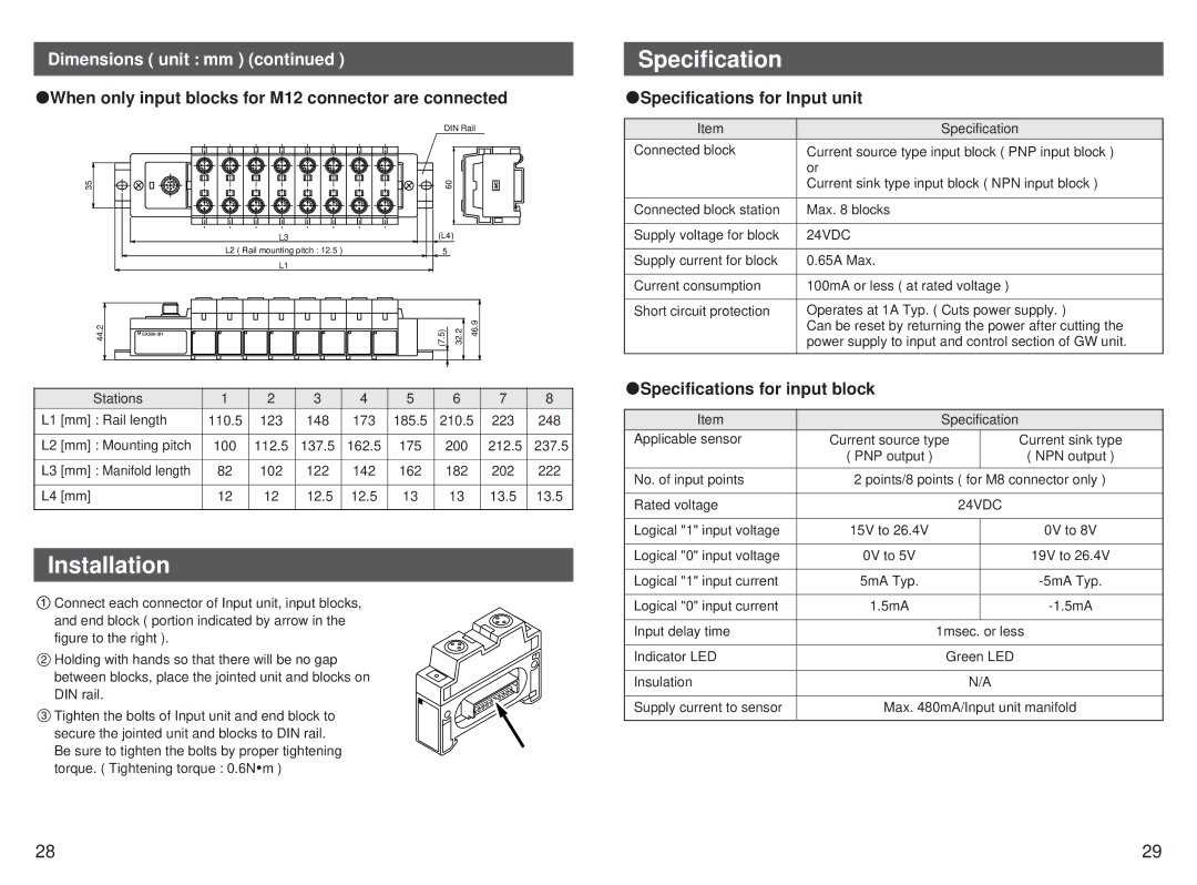
DIN Rail
35 | 60 |
L3 | (L4) |
L2 ( Rail mounting pitch : 12.5 ) | 5 |
L1 |
|
44.2 | (7.5) | 32.2 | 46.9 |
| Stations | 1 | 2 | 3 | 4 | 5 | 6 | 7 | 8 |
L1 | [mm] : Rail length | 110.5 | 123 | 148 | 173 | 185.5 | 210.5 | 223 | 248 |
|
|
|
|
|
|
|
|
|
|
L2 | [mm] : Mounting pitch | 100 | 112.5 | 137.5 | 162.5 | 175 | 200 | 212.5 | 237.5 |
|
|
|
|
|
|
|
|
|
|
L3 | [mm] : Manifold length | 82 | 102 | 122 | 142 | 162 | 182 | 202 | 222 |
|
|
|
|
|
|
|
|
|
|
L4 | [mm] | 12 | 12 | 12.5 | 12.5 | 13 | 13 | 13.5 | 13.5 |
|
|
|
|
|
|
|
|
|
|
Installation
![]() Connect each connector of Input unit, input blocks, and end block ( portion indicated by arrow in the figure to the right ).
Connect each connector of Input unit, input blocks, and end block ( portion indicated by arrow in the figure to the right ).
![]() Holding with hands so that there will be no gap between blocks, place the jointed unit and blocks on DIN rail.
Holding with hands so that there will be no gap between blocks, place the jointed unit and blocks on DIN rail.
![]() Tighten the bolts of Input unit and end block to secure the jointed unit and blocks to DIN rail. Be sure to tighten the bolts by proper tightening torque. ( Tightening torque : 0.6N
Tighten the bolts of Input unit and end block to secure the jointed unit and blocks to DIN rail. Be sure to tighten the bolts by proper tightening torque. ( Tightening torque : 0.6N![]() m )
m )
Specification
 Specifications for Input unit
Item | Specification |
Connected block | Current source type input block ( PNP input block ) |
| or |
| Current sink type input block ( NPN input block ) |
|
|
Connected block station | Max. 8 blocks |
|
|
Supply voltage for block | 24VDC |
|
|
Supply current for block | 0.65A Max. |
|
|
Current consumption | 100mA or less ( at rated voltage ) |
|
|
Short circuit protection | Operates at 1A Typ. ( Cuts power supply. ) |
| Can be reset by returning the power after cutting the |
| power supply to input and control section of GW unit. |
|
|
 Specifications for input block
Item | Specification |
| |
Applicable sensor | Current source type |
| Current sink type |
| ( PNP output ) |
| ( NPN output ) |
|
|
| |
No. of input points | 2 points/8 points ( for M8 connector only ) | ||
|
|
| |
Rated voltage | 24VDC |
| |
|
|
| |
Logical "1" input voltage | 15V to 26.4V |
| 0V to 8V |
|
|
|
|
Logical "0" input voltage | 0V to 5V |
| 19V to 26.4V |
|
|
|
|
Logical "1" input current | 5mA Typ. |
| |
|
|
|
|
Logical "0" input current | 1.5mA |
| |
|
|
| |
Input delay time | 1msec. or less | ||
|
|
| |
Indicator LED | Green LED |
| |
|
|
| |
Insulation | N/A |
| |
|
| ||
Supply current to sensor | Max. 480mA/Input unit manifold | ||
|
|
|
|
28 | 29 |