SAFETY ( continued )
Follow the instructions given below when handling your reduced wiring system. Otherwise a damage or failure to cause a malfunction can result.
![]() Operate the reduced wiring system at the specified voltage.
Operate the reduced wiring system at the specified voltage.
![]() Reserve space for maintenance.
Reserve space for maintenance.
![]() Do not remove any name plate or label.
Do not remove any name plate or label.
![]() Do not drop, hit or apply an excessive shock to the unit.
Do not drop, hit or apply an excessive shock to the unit.
![]() Follow the specified tightening torque.
Follow the specified tightening torque.
![]() Do not apply any excessive force to cables by repeated bending, tensioning or placing a heavy object on the cables.
Do not apply any excessive force to cables by repeated bending, tensioning or placing a heavy object on the cables.
![]() Connect wires and cables correctly.
Connect wires and cables correctly.
![]() Do not perform any wiring work while the power is on.
Do not perform any wiring work while the power is on.
![]() Do not use the reduced wiring system on the same wiring route as the power line or high voltage line.
Do not use the reduced wiring system on the same wiring route as the power line or high voltage line.
![]() Confirm the insulation of wiring.
Confirm the insulation of wiring.
![]() Perform the power supply wiring by dividing into two lines
Perform the power supply wiring by dividing into two lines
and the other is for power supply for input and controlling GW/SI.
![]() Take sufficient measures against noise such as noise filter when incorporating the reduced wiring system into a machine or equipment.
Take sufficient measures against noise such as noise filter when incorporating the reduced wiring system into a machine or equipment.
![]() Mount a terminal plug or a waterproof cap on each unused M12 connector for input/output ( communication connector, communication ports A - D, and power supply for input and controlling GW/SI ).
Mount a terminal plug or a waterproof cap on each unused M12 connector for input/output ( communication connector, communication ports A - D, and power supply for input and controlling GW/SI ).
Product Summary
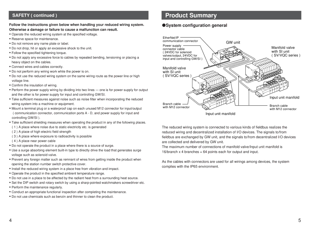
 System configuration general
EtherNet/IP |
| |
communication connector | GW unit | |
Power supply | ||
| ||
connector cable |
| |
( 24VDC for solenoid |
| |
valves/output, 24VDC for |
| |
input and controlling GW/SI ) |
|
Manifold valve with SI unit
( SV/VQC series )
Branch cable
with M12 connector
Input unit manifold
Manifold valve with SI unit
( SV/VQC series )
Input unit manifold
Branch cable
with M12 connector
![]() Take sufficient shielding measures when operating the product in any of the following places. ( 1 ) A place where noise due to static electricity etc. is generated
Take sufficient shielding measures when operating the product in any of the following places. ( 1 ) A place where noise due to static electricity etc. is generated
( 2 ) A place of high electric field strength
( 3 ) A place where exposure to radioactivity is possible
( 4 ) A place near power cable
![]() Do not operate the product in a place where there is a source of surge.
Do not operate the product in a place where there is a source of surge.
![]() Use a surge absorbing element
Use a surge absorbing element
![]() Prevent any foreign matter such as remnant of wires from getting inside the product when opening the station number switch protective cover.
Prevent any foreign matter such as remnant of wires from getting inside the product when opening the station number switch protective cover.
![]() Install the reduced wiring system in a place free from vibration and impact.
Install the reduced wiring system in a place free from vibration and impact.
![]() Operate the product in the specified ambient temperature range.
Operate the product in the specified ambient temperature range.
![]() Do not use in a place to be affected by the radiant heat from a surrounding heat source.
Do not use in a place to be affected by the radiant heat from a surrounding heat source.
![]() Set the DIP switch and rotary switch by using a
Set the DIP switch and rotary switch by using a
![]() Perform the maintenance regularly.
Perform the maintenance regularly.
![]() Conduct an appropriate functional inspection after completing the maintenance.
Conduct an appropriate functional inspection after completing the maintenance. ![]() Do not use chemicals such as benzin and thinner to clean the product.
Do not use chemicals such as benzin and thinner to clean the product.
The reduced wiring system is connected to various kinds of fieldbus realizes the reduced wiring and decentralized installation of I/O devices. The signals to/from fieldbus are exchanged by GW unit, and the signals to/from decentralized I/O devices are collected and delivered by GW unit.
The maximum number of connections of manifold valve/Input unit manifold is 16/branch x 4 branches = 64 points each for output and input.
As the cables with connectors are used for all wirings among devices, the system complies with the IP65 environment.
4 | 5 |