Mounting
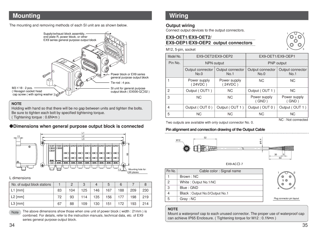
The mounting and removing methods of each SI unit are as shown below.
Supply/exhaust block assembly, ![]() end plate R, power block, or other
end plate R, power block, or other
EX9 series general purpose output block
Wiring
Output wiring
Connect output devices to the output connectors.
| 1 | 2 | |
5 |
| ||
|
| ||
M12, | 4 | 3 | |
Model No. |
|
|
|
Pin No. | NPN output | PNP output |
|
| Output connector Output connector | Output connector Output connector | |
M3 ![]() 18 : 2 pcs.
18 : 2 pcs.
( Hexagon socket head
cap screw ( with spring washer ))
Power block or EX9 series general purpose output block
SI unit for general purpose output block ( ![]() 02
02
| No.0 | No.1 | No.0 | No.1 |
|
|
|
|
|
1 | Power supply | Power supply | NC | NC |
| ( 24VDC ) | ( 24VDC ) |
|
|
|
|
|
|
|
2 | Output ( OUT1 ) | NC | Output ( OUT 1 ) | NC |
|
|
|
|
|
3 | NC | NC | Power supply | Power supply |
|
|
| ( GND ) | ( GND ) |
NOTE
Holding with hand so that there will be no gap between units and tighten the bolts. Be sure to tighten each bolt by specified tightening torque.
( Tightening torque : 0.6N![]() m )
m )
 Dimensions when general purpose output block is connected
|
|
|
| L1 |
|
|
|
|
|
|
13 |
|
|
| L2 |
|
|
|
|
|
|
|
|
|
| L3 |
|
|
|
|
|
|
PWR | PWR |
|
|
|
|
|
|
|
|
|
COM |
|
|
|
|
|
|
|
|
|
|
| 0 | 0 | 0 | 0 | 0 | 0 | 0 | 0 | 66 |
|
|
|
|
|
|
|
|
|
|
| |
| 1 | 1 | 1 | 1 | 1 | 1 | 1 | 1 |
|
|
| PWR |
|
|
|
|
|
|
|
|
|
EX500 |
|
|
|
|
|
|
|
|
|
|
series |
|
|
|
|
|
|
|
|
|
|
|
|
|
|
|
|
|
| 1.5 | Mounting hole for: | |
|
|
|
|
|
|
|
|
| M4 places |
|
L dimensions |
|
|
|
|
|
|
|
|
|
|
No. of output block stations | 1 | 2 |
| 3 |
| 4 | 5 | 6 | 7 | 8 |
L1 [mm] | 83 | 104 |
| 125 |
| 146 | 167 | 188 | 209 | 230 |
L2 [mm] | 72 | 93 |
| 114 |
| 135 | 156 | 177 | 198 | 219 |
L3 [mm] | 67 | 88 |
| 109 |
| 130 | 151 | 172 | 193 | 214 |
Note | The above dimensions show those when one unit of power block ( width : 21mm ) is | |
combined. For details, refer to the instruction manuals, technical data, etc. of EX9 | ||
| ||
| series general purpose output block. |
4 | Output ( OUT 0 ) | Output ( OUT 1 ) | Output ( OUT 0 ) | Output ( OUT 1 ) |
|
|
|
|
|
5 | NC | NC | NC | NC |
|
|
|
|
|
|
|
|
| NC : Not connected |
Two outputs are available with only output connector No. 0.
Pin alignment and connection drawing of the Output Cable
| 52 | 6.4φ |
|
| M12 |
| |
|
|
| |
|
| 30 | 5 |
|
| 50 |
|
|
|
| |
Pin No. | Cable color : Signal name | 1 | 2 |
|
| ||
1 | Brown : NC |
|
|
2 | White : Output No.1/NC |
| 5 |
|
| ||
3 | Blue : GND | 4 | 3 |
4 | Black : Output No.0/Output No.1 |
|
|
5 | Gray : NC | Plug connector pin layout | |
NOTE
Mount a waterproof cap to each unused connector. The proper use of waterproof cap can achieve IP65 Enclosure. ( Tightening torque for M12 : 0.1N![]() m )
m )
34 | 35 |