ABOUT THE TIGERSTACK III 10/100
LED | Condition | Status |
|
|
|
Stacking | On Green | This switch is acting as the master unit in the |
|
| stack. |
|
|
|
| Flashing Green | Initial state of stacking configuration to determine |
|
| whether the switch will act as a master or slave |
|
| unit. |
|
|
|
| On Amber | This switch is acting as a slave unit in the stack. |
|
|
|
Link/Act | On Green | LED display mode is Link/Act. |
|
|
|
PoE | On Green | LED display mode is PoE. |
|
|
|
| Off | Port LED display mode is Link/Act |
|
|
|
Stack Master Button
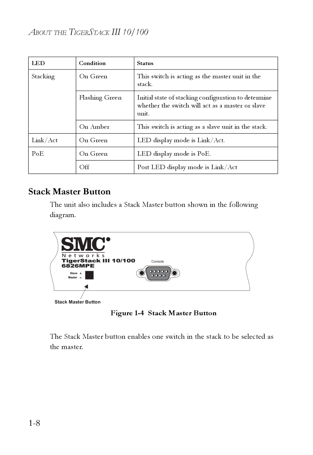
The unit also includes a Stack Master button shown in the following diagram.
Console
Stack Master Button
Figure 1-4 Stack Master Button
The Stack Master button enables one switch in the stack to be selected as the master.