CONNECTIVITY RULES
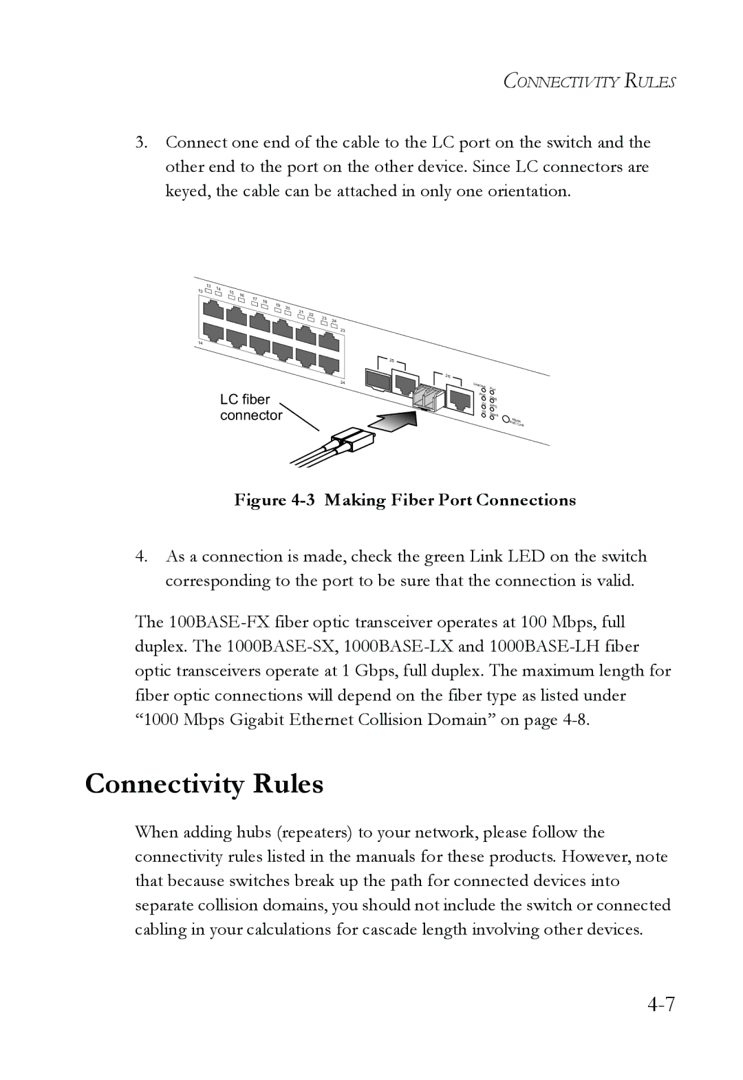
3.Connect one end of the cable to the LC port on the switch and the other end to the port on the other device. Since LC connectors are keyed, the cable can be attached in only one orientation.
| 13 | 14 |
|
|
|
|
|
|
|
|
|
13 |
| 15 |
|
|
|
|
|
|
|
| |
|
| 16 |
|
|
|
|
|
|
| ||
|
|
|
| 17 |
|
|
|
|
|
| |
|
|
|
|
| 18 |
|
|
|
|
| |
|
|
|
|
|
| 19 |
|
|
|
| |
|
|
|
|
|
|
| 20 |
|
|
| |
|
|
|
|
|
|
|
| 21 | 22 |
|
|
|
|
|
|
|
|
|
|
| 23 |
| |
|
|
|
|
|
|
|
|
|
| 24 | |
|
|
|
|
|
|
|
|
|
|
| |
|
|
|
|
|
|
|
|
|
|
| 23 |
14 |
|
|
|
|
|
|
|
|
|
|
|
|
|
|
|
|
|
|
|
|
|
| 25 |
|
|
|
|
|
|
|
|
|
|
| 24 |
LC fiber connector
26
Link/Act | Pwr |
| |
PoE | Diag |
|
25RPS
26Stack
Mod | e | |
Po |
| |
| E /Link | |
Figure 4-3 Making Fiber Port Connections
4.As a connection is made, check the green Link LED on the switch corresponding to the port to be sure that the connection is valid.
The
Connectivity Rules
When adding hubs (repeaters) to your network, please follow the connectivity rules listed in the manuals for these products. However, note that because switches break up the path for connected devices into separate collision domains, you should not include the switch or connected cabling in your calculations for cascade length involving other devices.