DESCRIPTION OF HARDWARE
Port and System Status LED Indicators
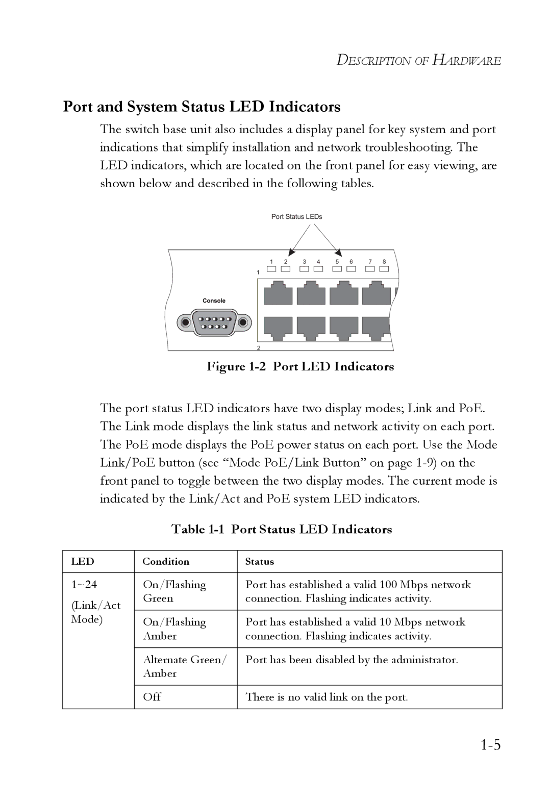
The switch base unit also includes a display panel for key system and port indications that simplify installation and network troubleshooting. The LED indicators, which are located on the front panel for easy viewing, are shown below and described in the following tables.
Port Status LEDs
1 | 2 | 3 | 4 | 5 | 6 | 7 | 8 |
1
2
Figure 1-2 Port LED Indicators
The port status LED indicators have two display modes; Link and PoE. The Link mode displays the link status and network activity on each port. The PoE mode displays the PoE power status on each port. Use the Mode Link/PoE button (see “Mode PoE/Link Button” on page
Table 1-1 Port Status LED Indicators
LED | Condition | Status |
|
|
|
1~24 | On/Flashing | Port has established a valid 100 Mbps network |
(Link/Act | Green | connection. Flashing indicates activity. |
|
| |
Mode) | On/Flashing | Port has established a valid 10 Mbps network |
| Amber | connection. Flashing indicates activity. |
|
|
|
| Alternate Green/ | Port has been disabled by the administrator. |
| Amber |
|
|
|
|
| Off | There is no valid link on the port. |
|
|
|