ABOUT THE TIGERSTACK III 10/100
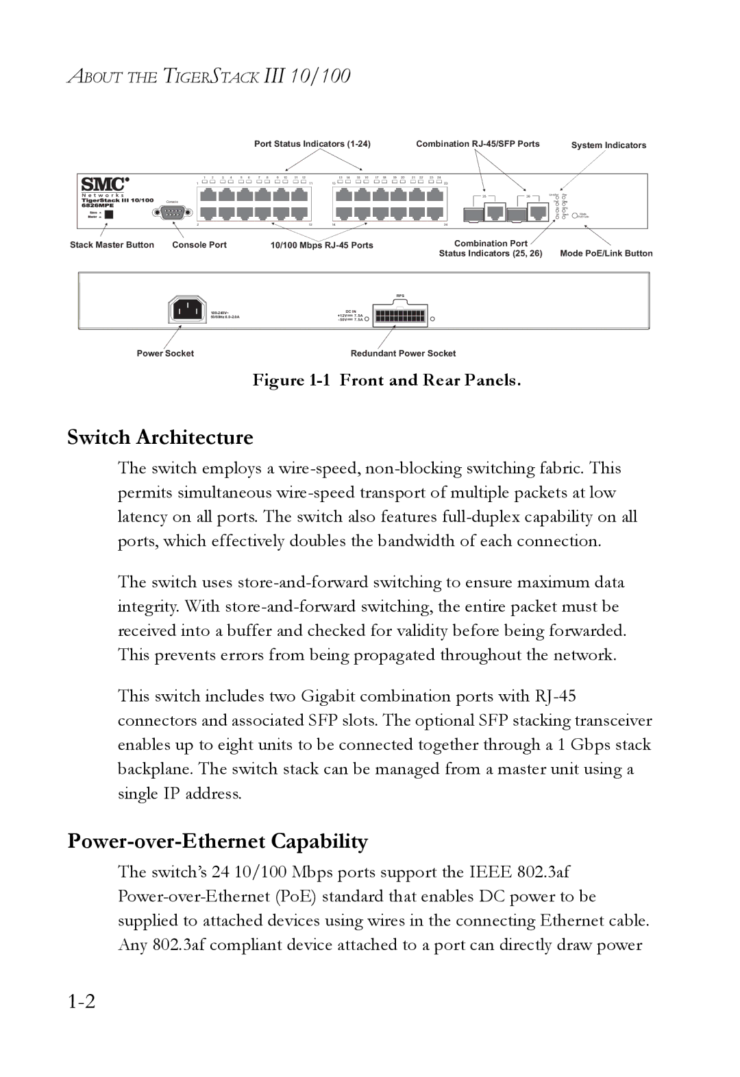
Port Status Indicators (1-24) | Combination RJ-45/SFP Ports | System Indicators |
1 | 2 | 3 | 4 | 5 | 6 | 7 | 8 | 9 | 10 | 11 | 12 | | 13 | 14 | 15 | 16 | 17 | 18 | 19 | 20 | 21 | 22 | 23 | 24 |
1 | | | | | | | | | | | | 11 | 13 | | | | | | | | | | | 23 |
Console
26Link/Act Pwr PoE Diag 25 RPS
2 1214
1214 24
24
Stack Master Button | Console Port | 10/100 Mbps RJ-45 Ports | Combination Port | |
| | | | Status Indicators (25, 26) | Mode PoE/Link Button |
| | | | RPS | |
| 100-240V~ | DC IN | | |
| 50/60Hz 8.0-2.0A | +12V | 7.5A | | |
| | - 50V | 7.5A | | |
Power Socket | | Redundant Power Socket | |
Figure 1-1 Front and Rear Panels.
Switch Architecture
The switch employs a wire-speed, non-blocking switching fabric. This permits simultaneous wire-speed transport of multiple packets at low latency on all ports. The switch also features full-duplex capability on all ports, which effectively doubles the bandwidth of each connection.
The switch uses store-and-forward switching to ensure maximum data integrity. With store-and-forward switching, the entire packet must be received into a buffer and checked for validity before being forwarded. This prevents errors from being propagated throughout the network.
This switch includes two Gigabit combination ports with RJ-45 connectors and associated SFP slots. The optional SFP stacking transceiver enables up to eight units to be connected together through a 1 Gbps stack backplane. The switch stack can be managed from a master unit using a single IP address.
Power-over-Ethernet Capability
The switch’s 24 10/100 Mbps ports support the IEEE 802.3af Power-over-Ethernet (PoE) standard that enables DC power to be supplied to attached devices using wires in the connecting Ethernet cable. Any 802.3af compliant device attached to a port can directly draw power