INSTALLING THE SWITCH
Connecting Switches in a Stack
| 13 | 14 |
|
|
|
|
|
|
|
|
13 |
| 15 | 16 |
|
|
|
|
|
| |
|
|
|
|
|
|
|
|
| ||
|
|
|
| 17 | 18 | 19 |
|
|
|
|
|
|
|
|
|
| 20 |
|
|
| |
|
|
|
|
|
|
| 21 | 22 | 23 |
|
|
|
|
|
|
|
|
|
| 24 | |
|
|
|
|
|
|
|
|
|
| 23 |
14 |
|
|
|
|
|
|
|
|
|
|
25
26
Tx
Rx
Link/Act PWR | |
PoE Diag | |
25 |
|
26 | Stacking |
| |
PoMEo/Ldeink
![]() Stack Master
Stack Master
| 13 | 14 |
|
|
|
|
|
|
|
|
13 |
| 15 | 16 |
|
|
|
|
|
| |
|
|
|
|
|
|
|
|
| ||
|
|
|
| 17 | 18 | 19 |
|
|
|
|
|
|
|
|
|
| 20 |
|
|
| |
|
|
|
|
|
|
| 21 | 22 | 23 |
|
|
|
|
|
|
|
|
|
| 24 | |
|
|
|
|
|
|
|
|
|
| 23 |
14 |
|
|
|
|
|
|
|
|
|
|
|
|
|
|
|
|
|
|
|
| 25 |
|
|
|
|
|
|
|
|
|
| 26 |
|
|
|
|
|
|
|
|
|
| Tx |
|
|
|
|
|
|
|
|
|
| Rx |
| 13 | 14 |
|
|
|
|
|
|
|
|
13 |
| 15 | 16 |
|
|
|
|
|
| |
|
|
|
| 17 | 18 | 19 |
|
|
|
|
|
|
|
|
|
| 20 |
|
|
| |
|
|
|
|
|
|
| 21 | 22 | 23 |
|
|
|
|
|
|
|
|
|
| 24 | |
|
|
|
|
|
|
|
|
|
| 23 |
14 |
|
|
|
|
|
|
|
|
|
|
|
|
|
|
|
|
|
|
|
| 25 |
|
|
|
|
|
|
|
|
|
| 26 |
|
|
|
|
|
|
|
|
|
| Tx |
|
|
|
|
|
|
|
|
|
| Rx |
Link/Act PWR | |
PoE Diag | |
25 |
|
26 | Stacking |
| |
PoMEo/Ldeink
Link/Act PWR | |
PoE Diag | |
25 |
|
26 | Stacking |
| |
PoMEo/Ldeink
![]() Slave
Slave
![]() Slave
Slave
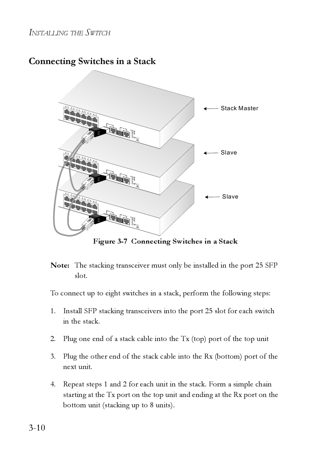
Figure 3-7 Connecting Switches in a Stack
Note: The stacking transceiver must only be installed in the port 25 SFP slot.
To connect up to eight switches in a stack, perform the following steps:
1.Install SFP stacking transceivers into the port 25 slot for each switch in the stack.
2.Plug one end of a stack cable into the Tx (top) port of the top unit
3.Plug the other end of the stack cable into the Rx (bottom) port of the next unit.
4.Repeat steps 1 and 2 for each unit in the stack. Form a simple chain starting at the Tx port on the top unit and ending at the Rx port on the bottom unit (stacking up to 8 units).