NETWORK PLANNING
Network Aggregation Plan
With 24 parallel bridging ports (i.e., 24 distinct collision domains), the switch can collapse a complex network down into a single efficient bridged node, increasing overall bandwidth and throughput.
When up to eight switch units are stacked together, they form a single “virtual” switch containing up to 200 ports. The whole stack can be managed through the Master unit using a single IP address.
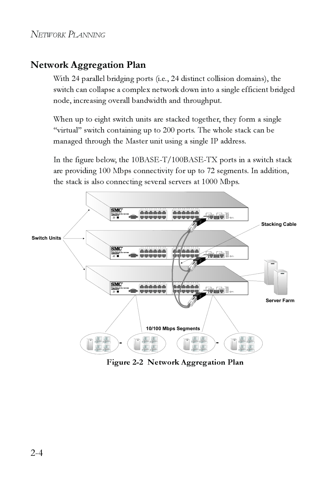
In the figure below, the 10BASE-T/100BASE-TX ports in a switch stack are providing 100 Mbps connectivity for up to 72 segments. In addition, the stack is also connecting several servers at 1000 Mbps.
Stacking Cable
Switch Units ![]()
Server Farm
10/100 Mbps Segments
... | ... |