INSTALLATION
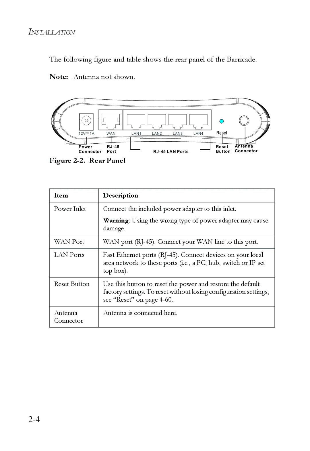
The following figure and table shows the rear panel of the Barricade.
Note: Antenna not shown.
12V 1A | WAN | LAN1 | LAN2 | LAN3 | LAN4 |
Power |
|
|
|
| |
Connector | Port |
|
| ||
Figure 2-2. Rear Panel
Reset Antenna Button Connector
Item | Description |
|
|
Power Inlet | Connect the included power adapter to this inlet. |
| Warning: Using the wrong type of power adapter may cause |
| damage. |
|
|
WAN Port | WAN port |
|
|
LAN Ports | Fast Ethernet ports |
| area network to these ports (i.e., a PC, hub, switch or IP set |
| top box). |
|
|
Reset Button | Use this button to reset the power and restore the default |
| factory settings. To reset without losing configuration settings, |
| see “Reset” on page |
|
|
Antenna | Antenna is connected here. |
Connector |
|
|
|