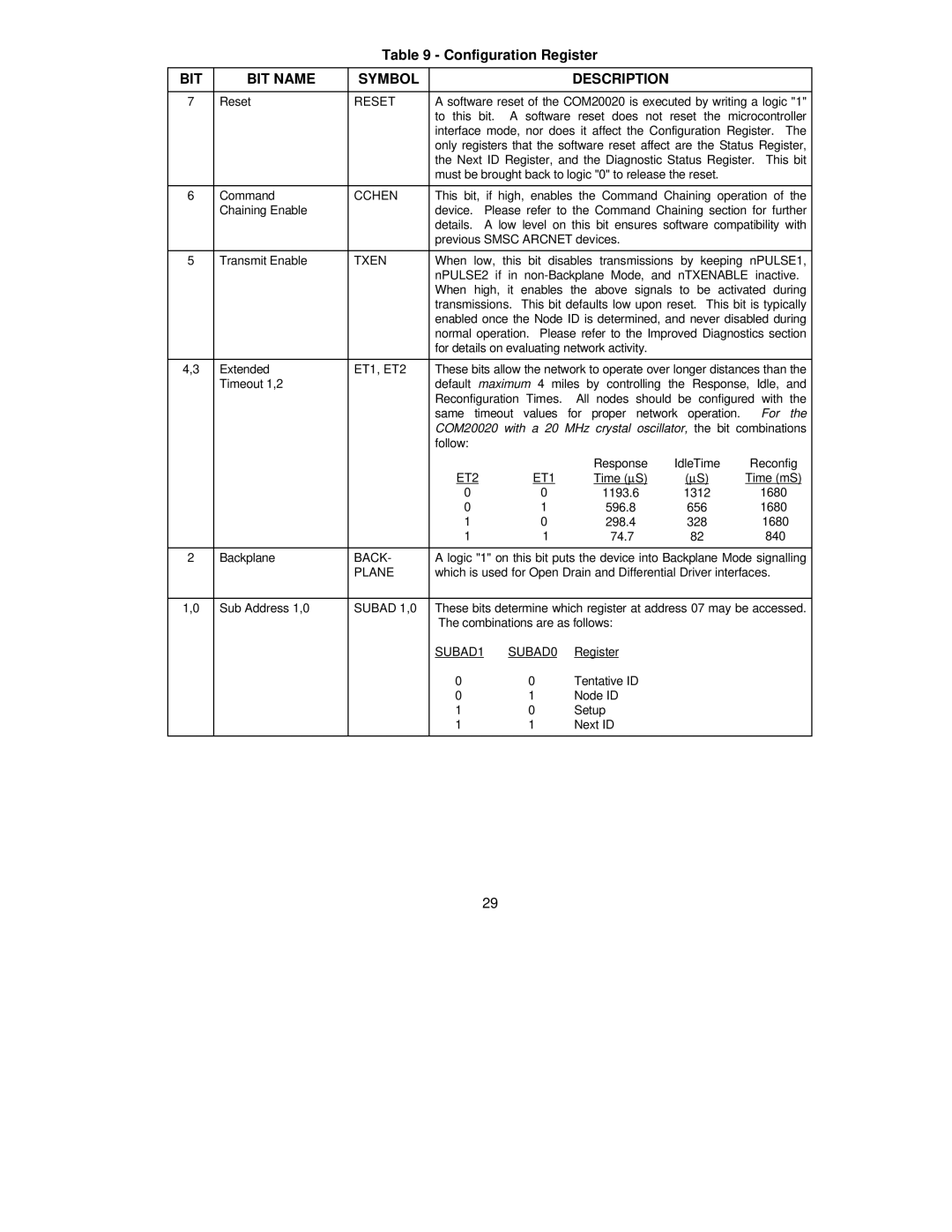
Table 9 - Configuration Register
BIT | BIT NAME | SYMBOL |
|
|
| DESCRIPTION |
| |
|
|
|
| |||||
7 | Reset | RESET | A software reset of the COM20020 is executed by writing a logic "1" | |||||
|
|
| to this bit. A software reset does not reset the microcontroller | |||||
|
|
| interface mode, nor does it affect the Configuration Register. The | |||||
|
|
| only registers that the software reset affect are the Status Register, | |||||
|
|
| the Next ID Register, and the Diagnostic Status Register. This bit | |||||
|
|
| must be brought back to logic "0" to release the reset. |
| ||||
|
|
|
| |||||
6 | Command | CCHEN | This bit, if high, enables the Command Chaining operation of the | |||||
| Chaining Enable |
| device. | Please refer to the Command Chaining section for further | ||||
|
|
| details. A low level on this bit ensures software compatibility with | |||||
|
|
| previous SMSC ARCNET devices. |
|
| |||
|
|
|
|
|
| |||
5 | Transmit Enable | TXEN | When | low, | this bit disables transmissions by keeping nPULSE1, | |||
|
|
| nPULSE2 if in | |||||
|
|
| When high, it enables the above signals to be activated during | |||||
|
|
| transmissions. This bit defaults low upon reset. This bit is typically | |||||
|
|
| enabled once the Node ID is determined, and never disabled during | |||||
|
|
| normal operation. Please refer to the Improved Diagnostics section | |||||
|
|
| for details on evaluating network activity. |
|
| |||
|
|
|
| |||||
4,3 | Extended | ET1, ET2 | These bits allow the network to operate over longer distances than the | |||||
| Timeout 1,2 |
| default maximum 4 miles by controlling | the Response, Idle, and | ||||
|
|
| Reconfiguration Times. All nodes should be configured with the | |||||
|
|
| same timeout values for proper network operation. For the | |||||
|
|
| COM20020 with a 20 MHz crystal oscillator, the bit combinations | |||||
|
|
| follow: |
|
|
|
|
|
|
|
|
|
|
| Response | IdleTime | Reconfig |
|
|
| ET2 | ET1 | Time (μS) | (μS) | Time (mS) | |
|
|
| 0 |
| 0 | 1193.6 | 1312 | 1680 |
|
|
| 0 |
| 1 | 596.8 | 656 | 1680 |
|
|
| 1 |
| 0 | 298.4 | 328 | 1680 |
|
|
| 1 |
| 1 | 74.7 | 82 | 840 |
|
|
|
| |||||
2 | Backplane | BACK- | A logic "1" on this bit puts the device into Backplane Mode signalling | |||||
|
| PLANE | which is used for Open Drain and Differential Driver interfaces. | |||||
|
|
|
| |||||
1,0 | Sub Address 1,0 | SUBAD 1,0 | These bits determine which register at address 07 may be accessed. | |||||
|
|
| The combinations are as follows: |
|
| |||
|
|
| SUBAD1 | SUBAD0 | Register |
|
| |
|
|
| 0 |
| 0 | Tentative ID |
|
|
|
|
| 0 |
| 1 | Node ID |
|
|
|
|
| 1 |
| 0 | Setup |
|
|
|
|
| 1 |
| 1 | Next ID |
|
|
|
|
|
|
|
|
|
|
|
29