t1
nCS
t3
nWR
VALID
t2
t4
t5
| Note 2 |
t6 | t5** |
| t7 |
VALID DATA |
|
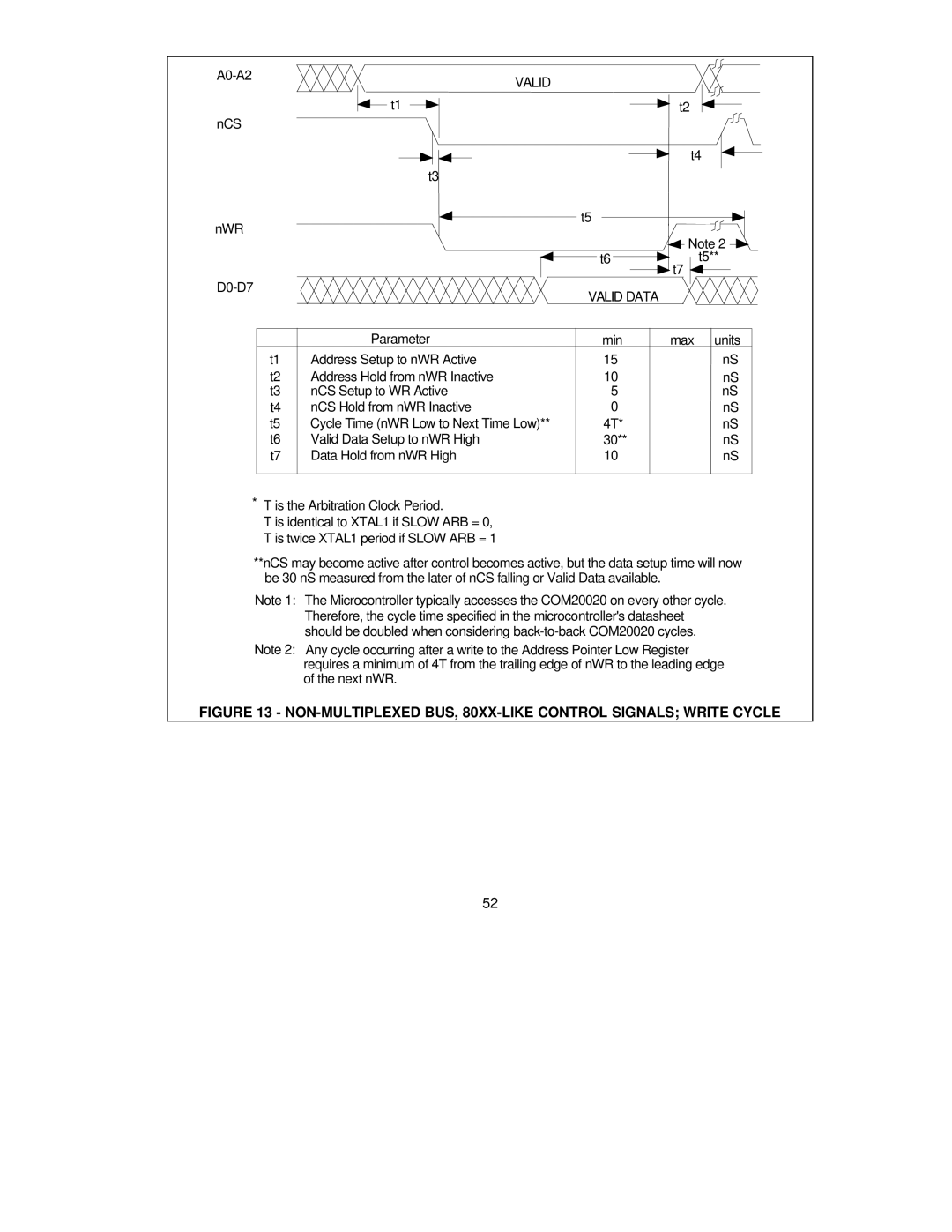
| Parameter | min | max units |
t1 | Address Setup to nWR Active | 15 | nS |
t2 | Address Hold from nWR Inactive | 10 | nS |
t3 | nCS Setup to WR Active | 5 | nS |
t4 | nCS Hold from nWR Inactive | 0 | nS |
t5 | Cycle Time (nWR Low to Next Time Low)** | 4T* | nS |
t6 | Valid Data Setup to nWR High | 30** | nS |
t7 | Data Hold from nWR High | 10 | nS |
|
|
|
|
*T is the Arbitration Clock Period.
T is identical to XTAL1 if SLOW ARB = 0, T is twice XTAL1 period if SLOW ARB = 1
**nCS may become active after control becomes active, but the data setup time will now be 30 nS measured from the later of nCS falling or Valid Data available.
Note 1: The Microcontroller typically accesses the COM20020 on every other cycle. Therefore, the cycle time specified in the microcontroller's datasheet should be doubled when considering
Note 2: Any cycle occurring after a write to the Address Pointer Low Register requires a minimum of 4T from the trailing edge of nWR to the leading edge of the next nWR.
FIGURE 13 - NON-MULTIPLEXED BUS, 80XX-LIKE CONTROL SIGNALS; WRITE CYCLE
52