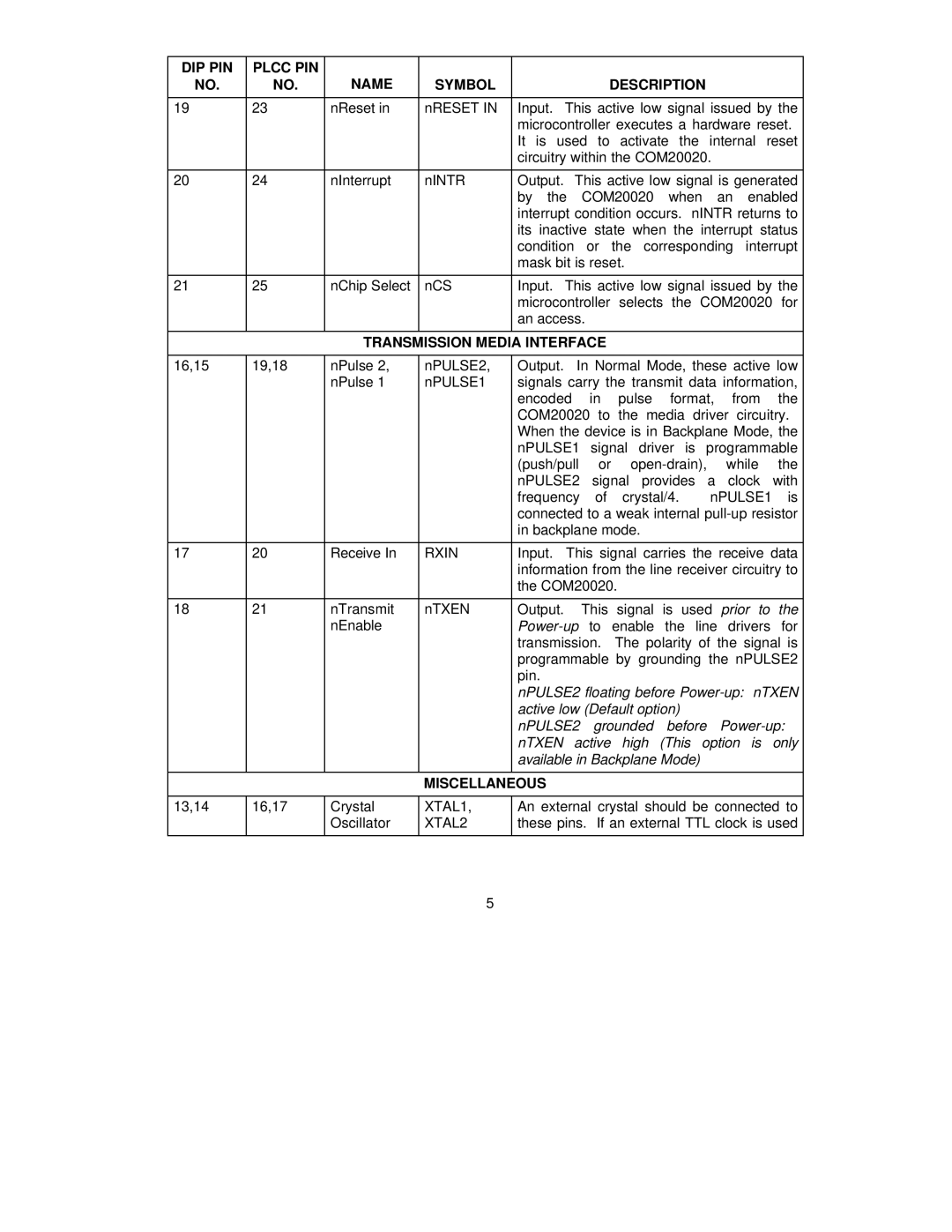
DIP PIN | PLCC PIN | NAME |
|
|
NO. | NO. | SYMBOL | DESCRIPTION | |
|
|
|
|
|
19 | 23 | nReset in | nRESET IN | Input. This active low signal issued by the |
|
|
|
| microcontroller executes a hardware reset. |
|
|
|
| It is used to activate the internal reset |
|
|
|
| circuitry within the COM20020. |
|
|
|
|
|
20 | 24 | nInterrupt | nINTR | Output. This active low signal is generated |
|
|
|
| by the COM20020 when an enabled |
|
|
|
| interrupt condition occurs. nINTR returns to |
|
|
|
| its inactive state when the interrupt status |
|
|
|
| condition or the corresponding interrupt |
|
|
|
| mask bit is reset. |
|
|
|
|
|
21 | 25 | nChip Select | nCS | Input. This active low signal issued by the |
|
|
|
| microcontroller selects the COM20020 for |
|
|
|
| an access. |
|
|
|
|
|
TRANSMISSION MEDIA INTERFACE
16,15 | 19,18 | nPulse 2, | nPULSE2, | Output. | In Normal Mode, these active low | |
|
| nPulse 1 | nPULSE1 | signals carry the transmit data information, | ||
|
|
|
| encoded in pulse format, from the | ||
|
|
|
| COM20020 to the media driver circuitry. | ||
|
|
|
| When the device is in Backplane Mode, the | ||
|
|
|
| nPULSE1 signal driver is programmable | ||
|
|
|
| (push/pull or | ||
|
|
|
| nPULSE2 signal provides a clock with | ||
|
|
|
| frequency of crystal/4. | nPULSE1 is | |
|
|
|
| connected to a weak internal | ||
|
|
|
| in backplane mode. |
| |
|
|
|
|
|
| |
17 | 20 | Receive In | RXIN | Input. | This signal carries the receive data | |
|
|
|
| information from the line receiver circuitry to | ||
|
|
|
| the COM20020. |
| |
|
|
|
|
|
| |
18 | 21 | nTransmit | nTXEN | Output. | This signal is used prior to the | |
|
| nEnable |
| |||
|
|
|
| transmission. The polarity of the signal is | ||
|
|
|
| programmable by grounding the nPULSE2 | ||
|
|
|
| pin. |
|
|
|
|
|
| nPULSE2 floating before | ||
|
|
|
| active low (Default option) |
| |
|
|
|
| nPULSE2 grounded before | ||
|
|
|
| nTXEN active high (This option is only | ||
|
|
|
| available in Backplane Mode) |
| |
|
|
|
|
|
|
|
|
|
| MISCELLANEOUS |
|
| |
|
|
|
|
| ||
13,14 | 16,17 | Crystal | XTAL1, | An external crystal should be connected to | ||
|
| Oscillator | XTAL2 | these pins. If an external TTL clock is used | ||
|
|
|
|
|
|
|
|
|
| 5 |
|
|
|