 NAMES AND FUNCTIONS OF PARTS
2
1 | 6 |
4
7
3
5
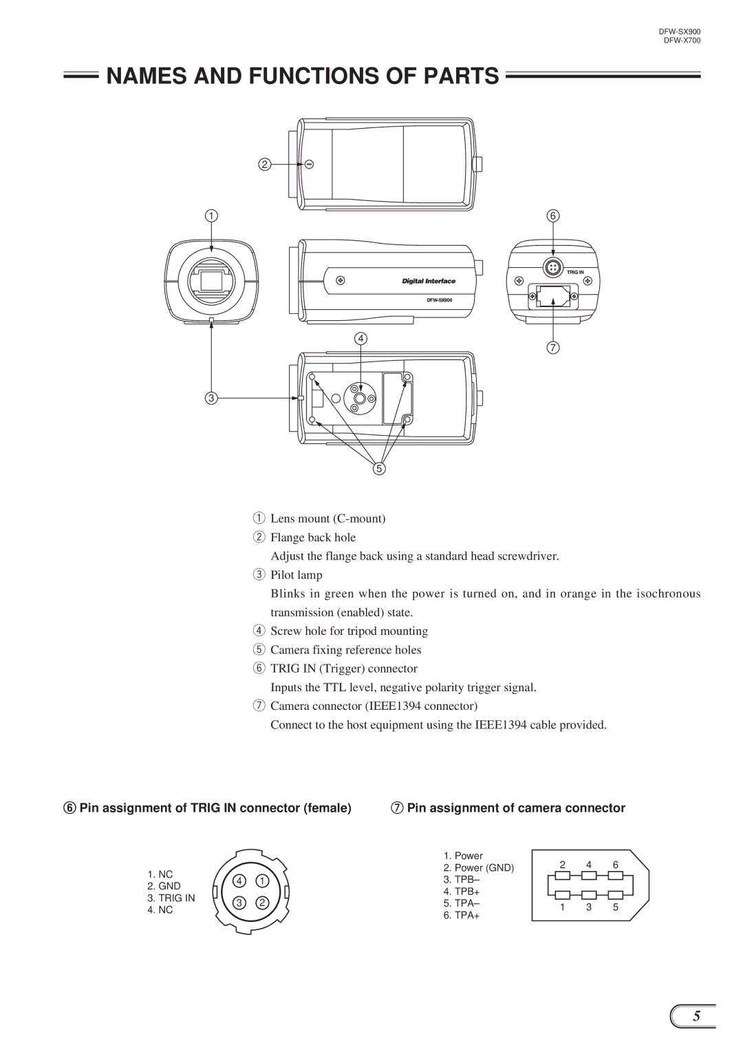
qLens mount
wFlange back hole
Adjust the flange back using a standard head screwdriver.
ePilot lamp
Blinks in green when the power is turned on, and in orange in the isochronous transmission (enabled) state.
rScrew hole for tripod mounting
tCamera fixing reference holes
yTRIG IN (Trigger) connector
Inputs the TTL level, negative polarity trigger signal.
uCamera connector (IEEE1394 connector)
Connect to the host equipment using the IEEE1394 cable provided.
yPin assignment of TRIG IN connector (female)
1. NC | 4 | 1 | |
2. GND | |||
|
| ||
3. TRIG IN | 3 | 2 | |
4. NC | |||
|
|
uPin assignment of camera connector
1. | Power | 2 | 4 | 6 |
|
| |||
2. | Power (GND) |
|
| ||||||
3. TPB– |
|
|
|
|
|
|
|
| |
|
|
|
|
|
|
|
| ||
4. TPB+ |
|
|
|
|
|
|
|
| |
|
|
|
|
|
|
|
| ||
5. TPA– |
|
|
|
|
|
|
|
| |
1 | 3 | 5 |
|
| |||||
|
|
|
| ||||||
6. TPA+
5
