Identifying parts and controls
See the pages in parentheses for further details.
Front | Rear | 5 |
|
| 6 |
|
|
|
|
|
|
|
|
|
|
|
| ||||||||||
|
|
|
|
|
|
|
|
|
|
|
|
|
|
|
|
| |||||||||||
|
|
|
|
|
|
|
|
|
|
|
|
|
|
|
|
|
|
|
|
|
|
|
|
|
|
|
|
|
|
|
|
|
|
|
|
|
|
|
|
|
|
|
|
|
|
|
|
|
|
|
|
|
|
|
|
|
|
|
|
|
|
|
|
|
|
|
|
|
|
|
|
|
|
|
|
|
|
|
|
|
|
|
|
|
|
|
|
|
|
|
|
|
|
|
|
|
|
|
|
|
|
|
|
|
|
|
|
|
|
|
|
| INPUT | MENU |
1 | 2 | OK |
12 3 4 | ||
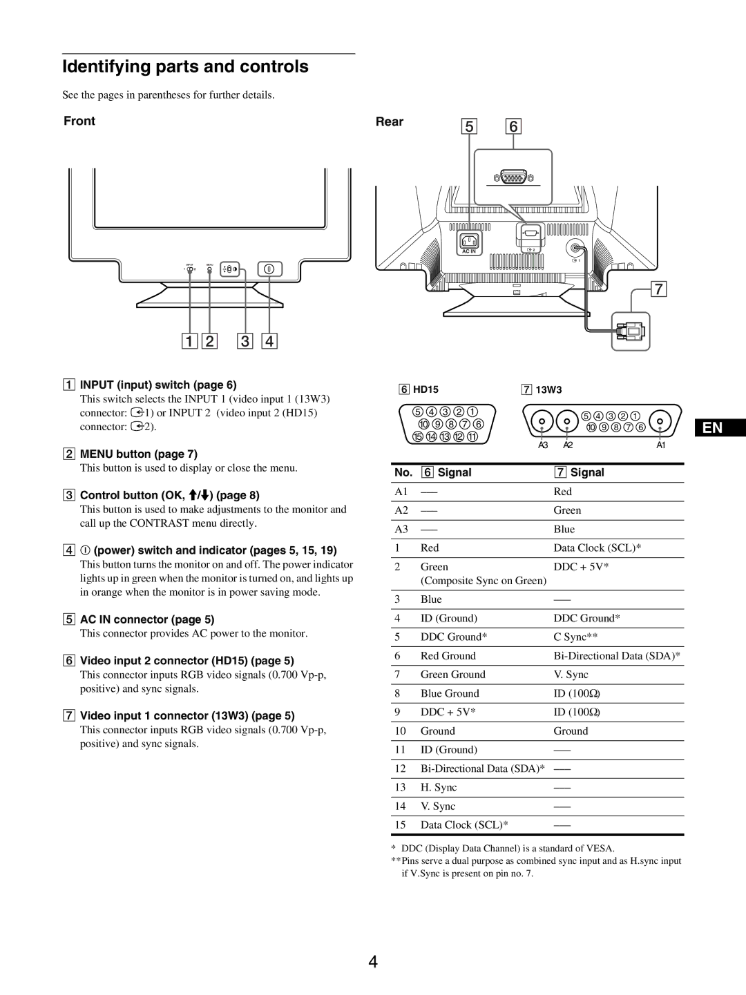
1INPUT (input) switch (page 6)
This switch selects the INPUT 1 (video input 1 (13W3) connector: y1) or INPUT 2 (video input 2 (HD15) connector: y2).
2MENU button (page 7)
This button is used to display or close the menu.
3Control button (OK, M/m) (page 8)
This button is used to make adjustments to the monitor and call up the CONTRAST menu directly.
4! (power) switch and indicator (pages 5, 15, 19)
This button turns the monitor on and off. The power indicator lights up in green when the monitor is turned on, and lights up in orange when the monitor is in power saving mode.
5AC IN connector (page 5)
This connector provides AC power to the monitor.
6Video input 2 connector (HD15) (page 5)
This connector inputs RGB video signals (0.700
7Video input 1 connector (13W3) (page 5)
This connector inputs RGB video signals (0.700
AC IN | 2 |
|
![]() 1
1
![]() 7
7
6 HD15 |
|
| 7 13W3 |
|
|
|
|
| |||||
5 |
|
| 4 | 3 | 2 | 1 | 5 | 4 | 3 | 2 | 1 |
| |
10 | 9 | 8 | 7 | 6 | EN | ||||||||
10 | 9 | 8 | 7 | 6 | |||||||||
15 | 14 | 13 12 | 11 | ||||||||||
A2 |
|
|
| A1 |
| ||||||||
|
|
|
|
|
| A3 |
|
|
|
| |||
No. | 6 Signal | 7 Signal |
|
|
|
| |||||||
A1 |
|
|
| Red |
|
|
|
|
| ||||
A2 |
|
|
| Green |
|
|
|
|
| ||||
A3 |
|
|
| Blue |
|
|
|
|
| ||||
1 | Red |
|
|
| Data Clock (SCL)* |
| |||||||
2 | Green |
|
| DDC + 5V* |
|
|
| ||||||
| (Composite Sync on Green) |
|
|
|
|
|
| ||||||
3 | Blue |
|
|
|
|
|
|
| |||||
4 | ID (Ground) | DDC Ground* |
|
|
| ||||||||
5 | DDC Ground* | C Sync** |
|
|
|
| |||||||
6 | Red Ground |
| |||||||||||
7 | Green Ground | V. Sync |
|
|
|
|
| ||||||
8 | Blue Ground | ID (100Ω) |
|
|
|
| |||||||
9 | DDC + 5V* | ID (100Ω) |
|
|
|
| |||||||
10 | Ground |
|
| Ground |
|
|
|
|
| ||||
11 | ID (Ground) |
|
|
|
|
| |||||||
12 |
|
|
|
|
| ||||||||
13 | H. Sync |
|
|
|
|
|
| ||||||
14 | V. Sync |
|
|
|
|
|
|
| |||||
15 | Data Clock (SCL)* |
|
|
|
|
| |||||||
* DDC (Display Data Channel) is a standard of VESA.
**Pins serve a dual purpose as combined sync input and as H.sync input if V.Sync is present on pin no. 7.
4