For Machines Mfg. Since 5/11 | I N T R O D U C T I O N | 14" |
|
|
|
Controls &
Components
Refer to Figures
Master Power Switch
The rotary switch shown in Figure 2 toggles incoming power ON and OFF to the lathe controls. It also prevents the electrical cabinet door from being opened when the switch is ON.
Main Power ![]()
Switch
Figure 2. Location of the master power switch.
Two-Speed Motor Switch
The
•Low (left position), enables speeds in the right headstock spindle speed chart
•OFF (middle position)
•High (right position), enables speeds in the left headstock spindle speed chart
![]()
Motor Switch
Figure 3. Location of the two-speed motor switch.
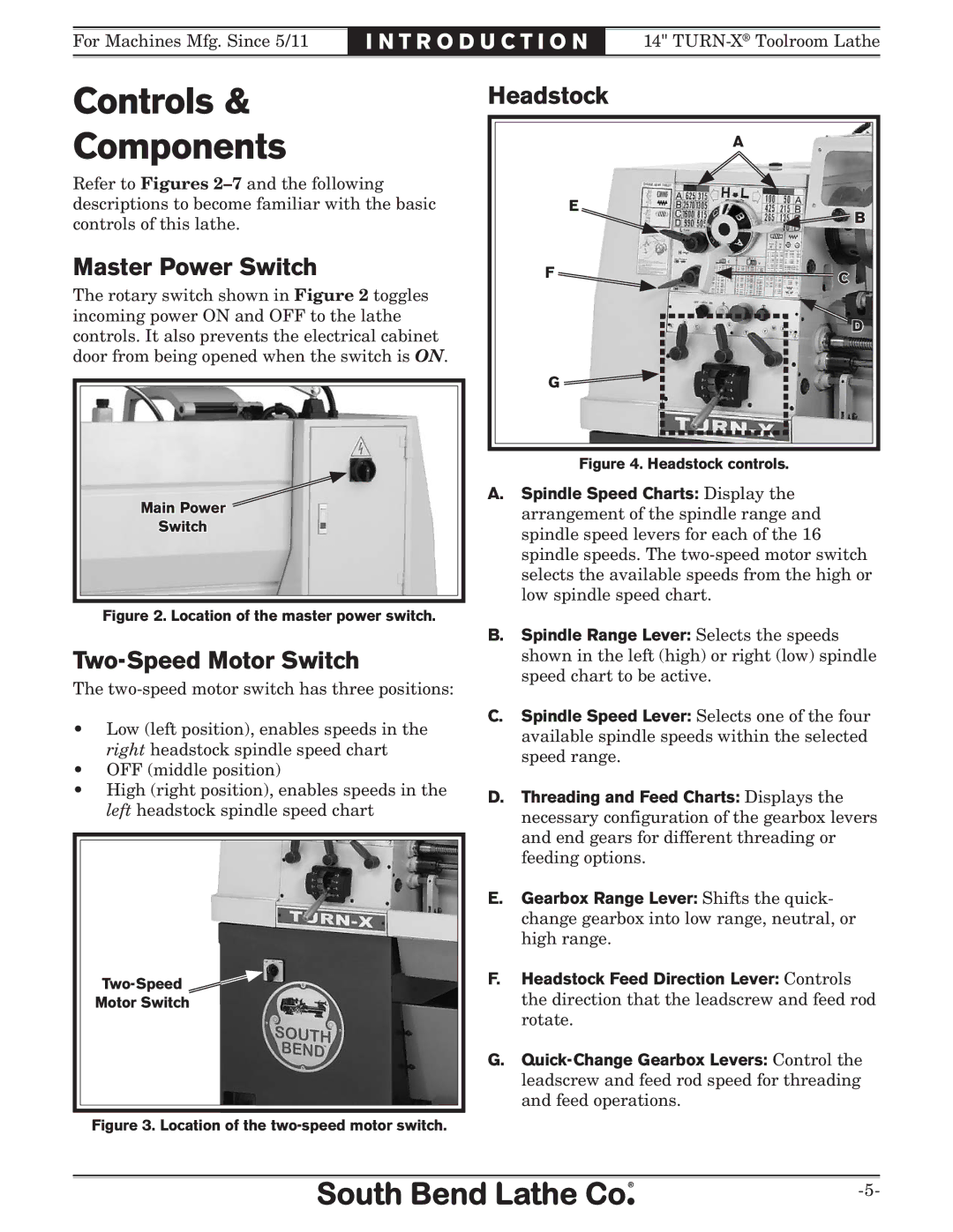
Headstock |
|
| A |
E | B |
| |
F | C |
| |
| D |
G |
|
Figure 4. Headstock controls.
A.Spindle Speed Charts: Display the arrangement of the spindle range and spindle speed levers for each of the 16 spindle speeds. The
B.Spindle Range Lever: Selects the speeds shown in the left (high) or right (low) spindle speed chart to be active.
C.Spindle Speed Lever: Selects one of the four available spindle speeds within the selected speed range.
D.Threading and Feed Charts: Displays the necessary configuration of the gearbox levers and end gears for different threading or feeding options.
E.Gearbox Range Lever: Shifts the quick- change gearbox into low range, neutral, or high range.
F.Headstock Feed Direction Lever: Controls the direction that the leadscrew and feed rod rotate.
G.