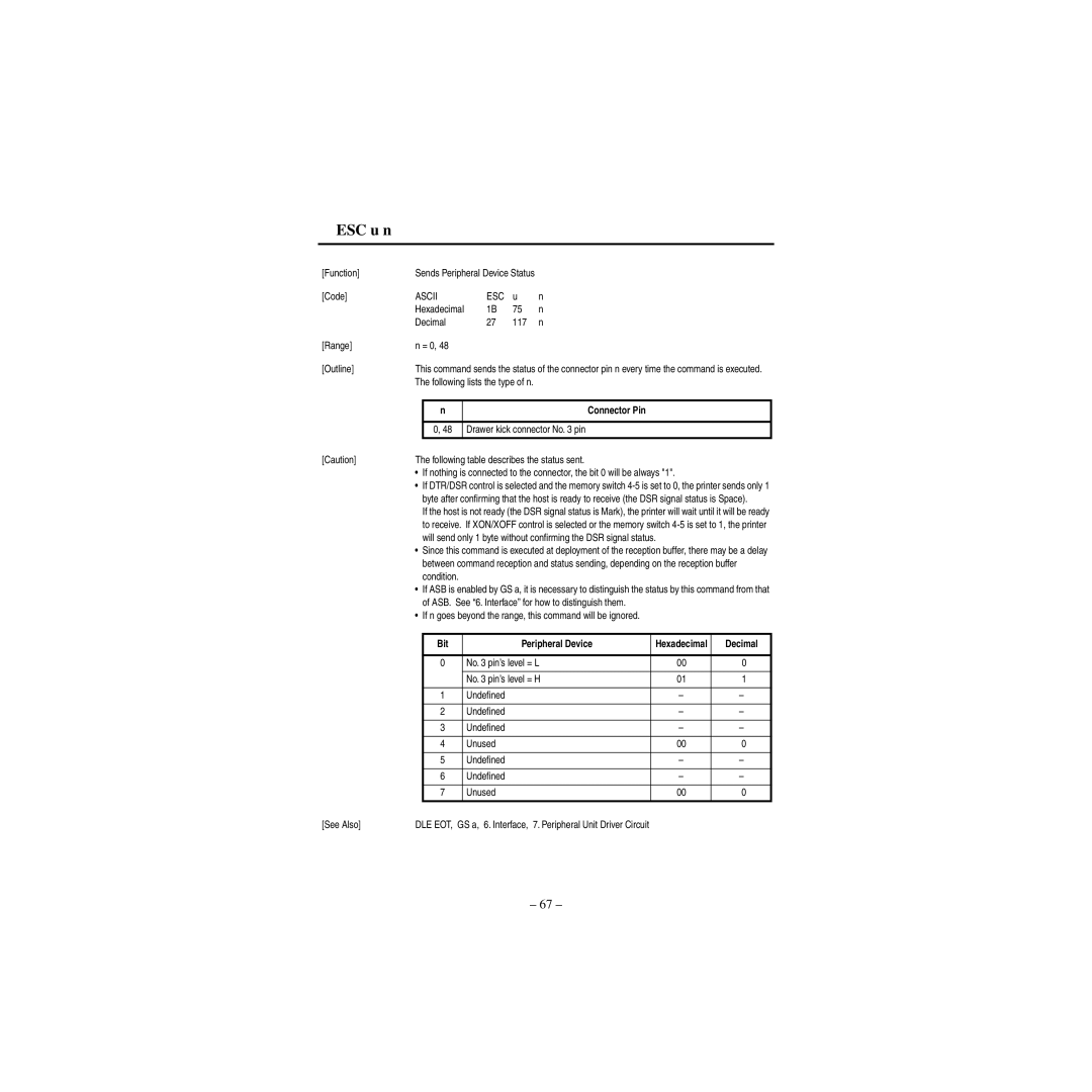
ESC u n
[Function] | Sends Peripheral Device Status |
| ||
[Code] | ASCII | ESC | u | n |
| Hexadecimal | 1B | 75 | n |
| Decimal | 27 | 117 | n |
[Range] | n = 0, 48 |
|
|
|
[Outline] | This command sends the status of the connector pin n every time the command is executed. | |||||
| The following lists the type of n. |
|
| |||
|
|
|
|
|
|
|
|
| n |
| Connector Pin |
|
|
|
|
|
|
|
| |
|
| 0, 48 | Drawer kick connector No. 3 pin |
|
| |
|
|
|
|
|
| |
[Caution] | The following table describes the status sent. |
|
| |||
| • | If nothing is connected to the connector, the bit 0 will be always "1". |
| |||
| • | If DTR/DSR control is selected and the memory switch | ||||
|
| byte after confirming that the host is ready to receive (the DSR signal status is Space). | ||||
|
| If the host is not ready (the DSR signal status is Mark), the printer will wait until it will be ready | ||||
|
| to receive. If XON/XOFF control is selected or the memory switch | ||||
|
| will send only 1 byte without confirming the DSR signal status. |
| |||
| • | Since this command is executed at deployment of the reception buffer, there may be a delay | ||||
|
| between command reception and status sending, depending on the reception buffer | ||||
|
| condition. |
|
| ||
| • | If ASB is enabled by GS a, it is necessary to distinguish the status by this command from that | ||||
|
| of ASB. See “6. Interface” for how to distinguish them. |
|
| ||
| • | If n goes beyond the range, this command will be ignored. |
|
| ||
|
|
|
|
|
|
|
|
| Bit |
| Peripheral Device | Hexadecimal | Decimal |
|
|
|
|
|
|
|
|
| 0 |
| No. 3 pin’s level = L | 00 | 0 |
|
|
|
|
|
|
|
|
|
|
| No. 3 pin’s level = H | 01 | 1 |
|
|
|
|
|
|
|
|
| 1 |
| Undefined | – | – |
|
|
|
|
|
|
|
|
| 2 |
| Undefined | – | – |
|
|
|
|
|
|
|
|
| 3 |
| Undefined | – | – |
|
|
|
|
|
|
|
|
| 4 |
| Unused | 00 | 0 |
|
|
|
|
|
|
|
|
| 5 |
| Undefined | – | – |
|
|
|
|
|
|
|
|
| 6 |
| Undefined | – | – |
|
|
|
|
|
|
|
|
| 7 |
| Unused | 00 | 0 |
|
|
|
|
|
|
|
[See Also] | DLE EOT, | GS a, 6. Interface, 7. Peripheral Unit Driver Circuit |
|
| ||
– 67 –
