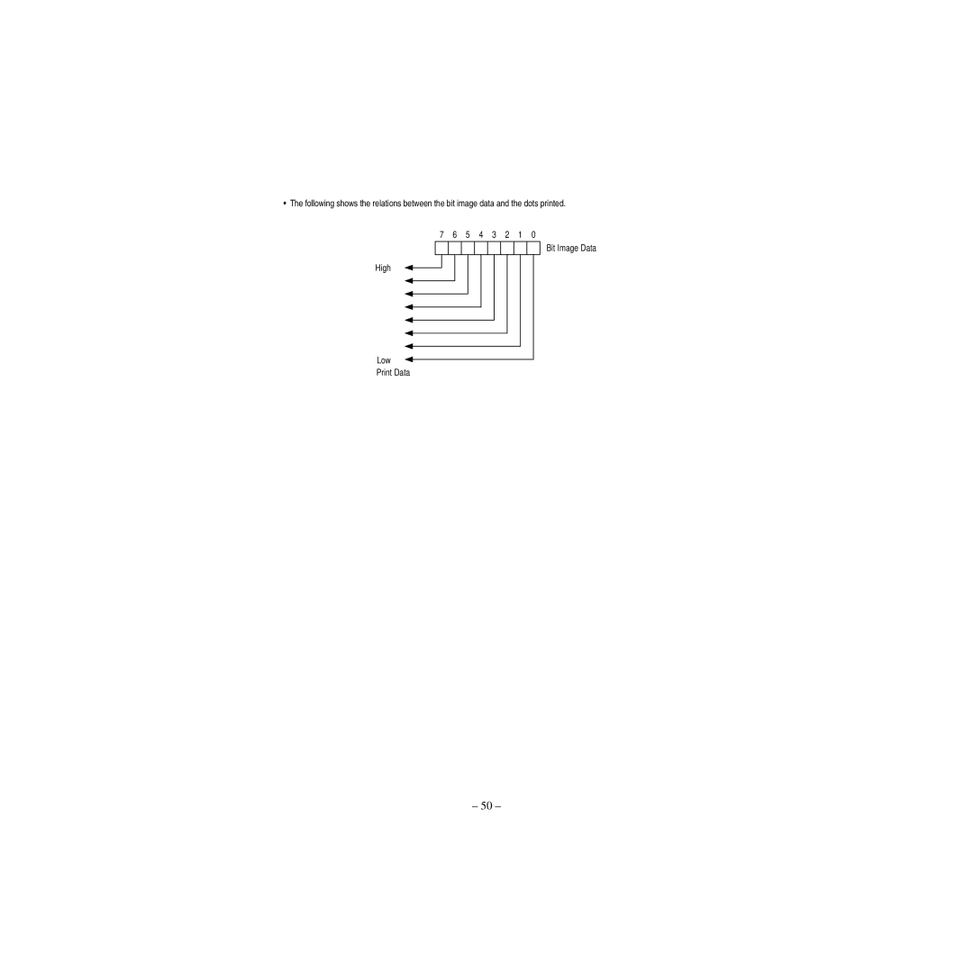
Page
Declaration of Conformity
IMPORTANT SAFETY INSTRUCTIONS
WICHTIGE SICHERHEITSANWEISUNGEN
For Uses in Canada
CAUTION Use shielded cable for this equipment Sicherheitshinweis
Pour L’utilisateurs Canadiens
CAUTIONS
BE SURE TO OBSERVE
SAFETY PRECAUTIONS
Do not connect/disconnect the AC adapter with wet hands
PRECAUTIONS FOR INSTALLATION
To Prevent Injury and Spreading of Damage
PRECAUTIONS FOR HANDLING
DAILY MAINTENANCE
1.1 Choosing a place for the printer
1. Printer Setup
Printer
1.2 Unpacking the printer
Ribbon cassette User’s Manual
Ferrite core Fastener AC Cable
tape tape
1.3 Removing the protective materials
General Specifications
Specifications
2.3 Paper Specifications and Print Area
2.2 Printing Specifications
Print Position
Adjustable in n/60″ units approximate
Paper Feed
Paper feed
2.4 Power Supply Specifications
3.1 General guide
3. Outer Appearance and Component Parts
4. Operation
4.2 Installing the ribbon cassette
4.1 Removing the printer cover
Replace the printer cover
Rotate the knob on the cassette again to take up any slack
4.3 Removing the ribbon cassette
4.4 Connecting to a power outlet and turning power on and off
Plug the other end of the power cord to a standard household wall outlet
Ferrite core 28 mm diameter Cable Interface
4.5 Connecting to your host computer
Pass the fastener through the ferrite core
4.6 Connecting to a peripheral unit
4.7 Inserting the paper into the printer
At least 3 cm Print start position mark
4.8 AutoSide Loading
Send data from your host computer to be printed on the paper
POWER
4.9.1 Indicator lights
4.9 Control Panel Operations
PAPER OUT
4.9.3 Producing a test print
4.9.4 Adjusting the dot alignment
This is caused when mechanical parts of the printer get out of alignment. This happens only rarely and you may never experience it at all throughout the life of the printer. If you do have problems, use the following procedure to correct it
4.9.5 Hexadecimal dump
1 Recoverable Errors
4.9.6 Errors
2 Non-recoverable Errors
3 Data Receive Error
4.10 Paper Sensors
Page
ON OFF
Switch
5.2 Available DIP switch settings
See table below
The table below shows the factory settings for the memory switches
5.3 Memory Switch Settings
Memory Switch
0000
6. Interface
6.1 Pins and Signal Names
D-sub 25 pin
6.2 Interface Connections
7.1 Modular plug
7. Peripheral Unit Driver Circuit
7.2 Drive circuit
North America
8. Maintenance and Service
Other Areas
9. Print Control Functions
9.1 List of ESC/POS Commands
Set Only setting is enabled Only part of setting is enabled
Enabled Line Enabled only at the head of the line
¢ Ignores partially Disabled An argument is processed as next data
Enables/Disables Automatic Status Sending
XXXX
9.2 Command Details
9.2.1 Description of Each Items
9.2.2 Command Details
Page Mode
Standard Mode
sequence of 10H04Hn 1 n
DLE EOT n
Decimal
Description
Description
Decimal
Decimal
Description
Description
ESC u, ESC v, GS a, 6. Interface
set print area
ESC SP n
ESC ! n
Sets Memory Switch
ESC #
Ignores
Description
ESC “q” Command Function
MSW5-D
MSW5-C
1B, the command selects the download character set
ESC % n
ESC & y c1 c2 xdyxxc2-c1+1
Example When selecting the 5 ⋅ 7 font p1 p2 p3 p4 p5 p6 MSB
Mode
ESC * m nL nH dk
Vertical Direction
7 6 5 4 3 2 1 Bit Image Data High Low Print Data
follows
ESC 3 n
ESC = n
ESC C n
ESC @
Initializes Printer
ESC D nk NUL
ESC J n
ESC F n
1B, the command selects reverse directional ejection
Decimal
ESC K n
This command switches from the standard mode to the page mode
ESC L
FF, 6. Interface
U.S.A
ESC R n
Spain
Japan
B ¤ ¤ ¤ ¤ ¤ ¤ ¤
ESC T n
dy = dyL + dyH ⋅
ESC W xL xH yL yH dxL dxH dyL dyH
ESC c 4 n
ESC d n
ESC c 5 n
ESC f t1 t2
ESC e n
Generates Specified Pulses
ESC p m t1 t2
m = 0, 1, 48
Memory Switch
ESC q
Selects Character Code Table
ESC t n
will send only 1 byte without confirming the DSR signal status
ESC u n
GS a, 2.3 Paper Specifications and Print Area
This command sends the status of the paper sensor when it is executed
ESC n
Description
GS I n
GS a n
Drawer kick connector No. 3 pin status = H
Drawer kick connector No. 3 pin status = L
Feeding the paper by the Paper Feed switch
The bits 5 and 6 of the 3rd byte will be turned to 1 no paper and
Sends the status of the drawer kick connector. Same as ESC u
GS r n
Sends Status
Status
1.1 Codepage PC437 USA, European Standard
1. Character Codes Table
1.2 Codepage Katakana Japanese
1.3 Codepage PC850 Multilingual
1.4 Codepage PC860 Portuguese
1.5 Codepage PC863 Canadian-French
1.6 Codepage PC865 Nordic
1.7 Codepage PC852 Eastern Europe
1.8 Codepage PC866 Russian
1.9 Codepage PC857 Turkish
1.10 Windows Codepage
1.11 Codepage PC858 Multilingual
Dimensions and Weight
Appendix 1 Outline Drawing of Printer CBM-820
Unit mm
Appendix 2 Outline Drawing of AC Adapter 31AD
AC ADAPTER
1500 +100
1.1 Wahl eines Aufstellungsorts für den Drucker
1. Drucker-Einrichtung
Hinweis
1.2 Auspacken des Druckers
Klebeband Klebeband
1.3 Entfernen der Schutzmaterialien
Wichtig
Allgemeine Daten
Technische Daten
Papier-Spezifikationen und Druckbereich
2.2 Druckspezifikationen
Zeichensatz
Zeichenmatrix
Papiervorschubrichtung
Wichtig
Letzte Druckzeile
fixiert
Wichtig
2.4 Technische Daten zur Netzversorgung
Eine Gleichspannungsquelle von 24 V ±5% und mehr als 1,9 A verwenden
3.1 Allgemeine Anleitung
3. Außenansicht und Bauteile
4.1 Abnehmen der Druckerabdeckung
4. Betrieb
4.2 Einsetzen der Farbbandkassette
Die Abdeckung aufsetzen
Hinweis
4.3 Entnehmen der Farbbandkassette
Wichtig
Den anderen Stecker des Netzkabels an eine Netzsteckdose anschließen
Wichtig
4.5 Anschließen an den Hostcomputer
Führen Sie den Kabelbinder durch den Ferritkern
Wichtig
4.6 Anschluß an ein Peripheriegerät
Wichtig
4.7 Papier in den Drucker einlegen
Wichtig
4.8 Automatischer Papiereinzug AutoSide Loading
Wichtig
Page
4.9.1 Anzeigeleuchten
4.9 Bedienfeld
POWER
PAPER OUT
FORWARD REVERSE RELEASE
4.9.2 Tasten
Schalten Sie den Drucker ein und legen Sie ein Blatt Papier ein
Hinweis
4.9.5 Sedezimaler Datenausdruck
Hinweis
Behebbare Fehler
4.9.6 Fehler
Nicht behebbare Fehler
3 Datenempfangsfehler
4.10 Papiersensoren
5.1 Zugang zu den DIP-Schaltern
5. DIP-Schaltereinstellung
Hinweis
Hinweis
Die Druckerabdeckung wieder ansetzen
5.2 Verwendbare DIP-Schaltereinstellungen
Wichtig
5.3 Einstellen der Speicherschalter
6. Schnittstelle
Stifte und Signalnamen
6.2 Schnittstellenanschlüsse
7.1 Modularstecker
7. Treiberschaltung für periphere Einheiten
Wichtig
Hinweis
7.2 Treiberschaltung
Nordamerika
8. Wartung und Dienst
Andere Gebiete