NOTE: Zero input corresponds to zero screw speed and no additive dosing. Maximum input corresponds to maximum screw speed.
NOTE: If a 0-10kHz frequency input is used, it must be a square wave with an amplitude of 12VDC. The shape of the signal is important, especially above 7,000Hz.
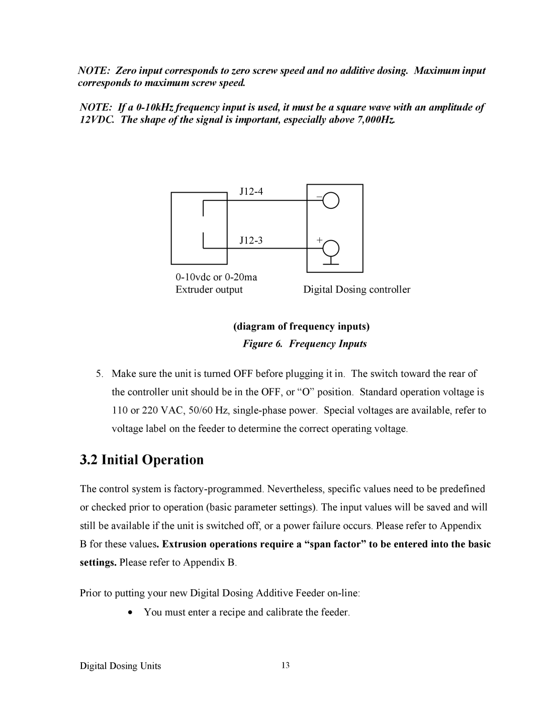
| | J12-3 | + | | | | |
| | | | | | | | |
| | | | | | | | |
0-10vdc or 0-20ma | | | | | | |
| | | | | |
Extruder output | Digital Dosing controller |
(diagram of frequency inputs)
Figure 6. Frequency Inputs
5.Make sure the unit is turned OFF before plugging it in. The switch toward the rear of the controller unit should be in the OFF, or “O” position. Standard operation voltage is 110 or 220 VAC, 50/60 Hz, single-phase power. Special voltages are available, refer to voltage label on the feeder to determine the correct operating voltage.
3.2Initial Operation
The control system is factory-programmed. Nevertheless, specific values need to be predefined or checked prior to operation (basic parameter settings). The input values will be saved and will still be available if the unit is switched off, or a power failure occurs. Please refer to Appendix B for these values. Extrusion operations require a “span factor” to be entered into the basic settings. Please refer to Appendix B.
Prior to putting your new Digital Dosing Additive Feeder on-line:
•You must enter a recipe and calibrate the feeder.