INSTALLATION INSTRUCTIONS
INSTALLATION
8.2.2 The appliance is factory set for top exit.
8.3A 152mm (6") diameter hole in the wall or ceiling is required to install the flue. This can be achieved by either:
a)Core drill
b)Hammer and chisel
•Drill small holes around the circumference when using method b. Make good both ends of the hole.
8.4• Allow enough room either above or to the side of the appliance to assemble the flue on top
•Assemble a horizontal flue in the following order:
-Vertical section
-90° elbow
-Horizontal plus terminal
•Support the opening of a masonry installation with a lintel
8.5Only the horizontal terminal section can be reduced in size.
To find the length:
•Measure from the outside of the wall to the stop on the
90°
•Add 10 mm to the outlet end
• Measure from the edge of the slots closest to the wall
• Mark around the flue, Diagram 31
31
10mm
AR0629
A wall plate is supplied to fix the flue to the wall:
•Bend the tab to 90°
•Assemble the plate onto the flue but wait to secure to wall and flue after the flue is fully assembled, Diagram 31
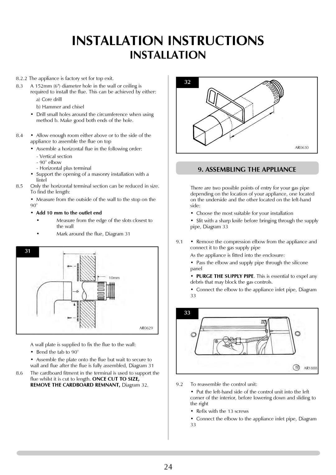
8.6The cardboard fitment in the terminal is used to support the flue whilst it is cut to length. ONCE CUT TO SIZE, REMOVE THE CARDBOARD REMNANT, Diagram 32.
32
AR0630
9. ASSEMBLING THE APPLIANCE
There are two possible points of entry for your gas pipe depending on the location of your appliance, one located on the underside and the other located on the
•Choose the most suitable for your installation
•Slit with a sharp knife before bringing through the supply pipe, Diagram 33
9.1• Remove the compression elbow from the appliance and connect it to the gas supply pipe
As the appliance is fitted into the enclosure:
•Pass the elbow and supply pipe through the silicone panel
•PURGE THE SUPPLY PIPE. This is essential to expel any debris that may block the gas controls.
•Connect the elbow to the appliance inlet pipe, Diagram
33
33
AR1888
9.2To reassemble the control unit:
•Put the
•Refix with the 13 screws
•Connect the elbow to the appliance inlet pipe, Diagram
33
24