SERVICING INSTRUCTIONS
REPLACING PARTS
9
AR1888
10
AR2135
With all screws removed:
•Slide the control unit to the left
•Lift the
11
AR2128
7.4 • Disconnect the two cables marked 'A' in Diagram 12
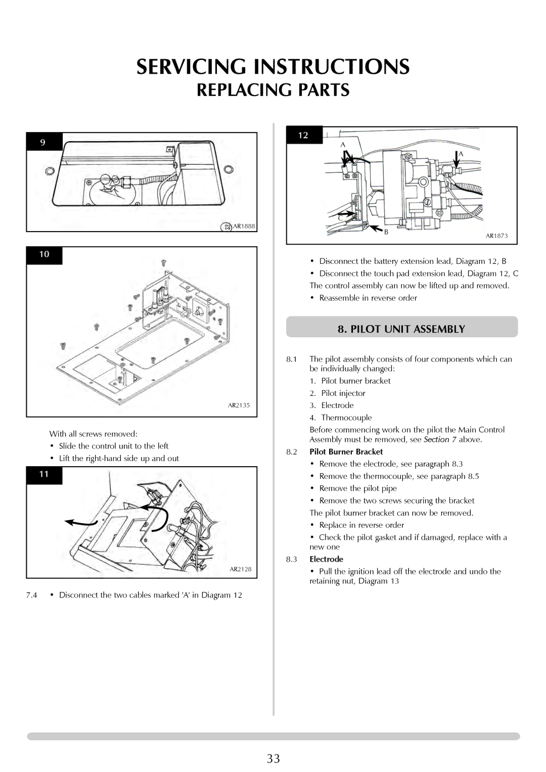
12 |
|
A |
|
| A |
C |
|
B | AR1873 |
|
•Disconnect the battery extension lead, Diagram 12, B
•Disconnect the touch pad extension lead, Diagram 12, C
The control assembly can now be lifted up and removed.
•Reassemble in reverse order
8.PILOT UNIT ASSEMBLY
8.1The pilot assembly consists of four components which can be individually changed:
1. Pilot burner bracket
2. Pilot injector
3. Electrode
4. Thermocouple
Before commencing work on the pilot the Main Control Assembly must be removed, see Section 7 above.
8.2Pilot Burner Bracket
•Remove the electrode, see paragraph 8.3
•Remove the thermocouple, see paragraph 8.5
•Remove the pilot pipe
•Remove the two screws securing the bracket
The pilot burner bracket can now be removed.
•Replace in reverse order
•Check the pilot gasket and if damaged, replace with a new one
8.3Electrode
•Pull the ignition lead off the electrode and undo the retaining nut, Diagram 13
33