INSTALLATION INSTRUCTIONS
INSTALLATION
9.3Remove the screw from the pressure test point
•Connect a suitable pressure gauge to the test point located on the inlet fitting
•Refit the burner
•Turn on the gas
•Light the appliance to check for leaks
•Turn off the gas
•Remove the burner
•Disconnect the pressure test point
•Replace the test point screw
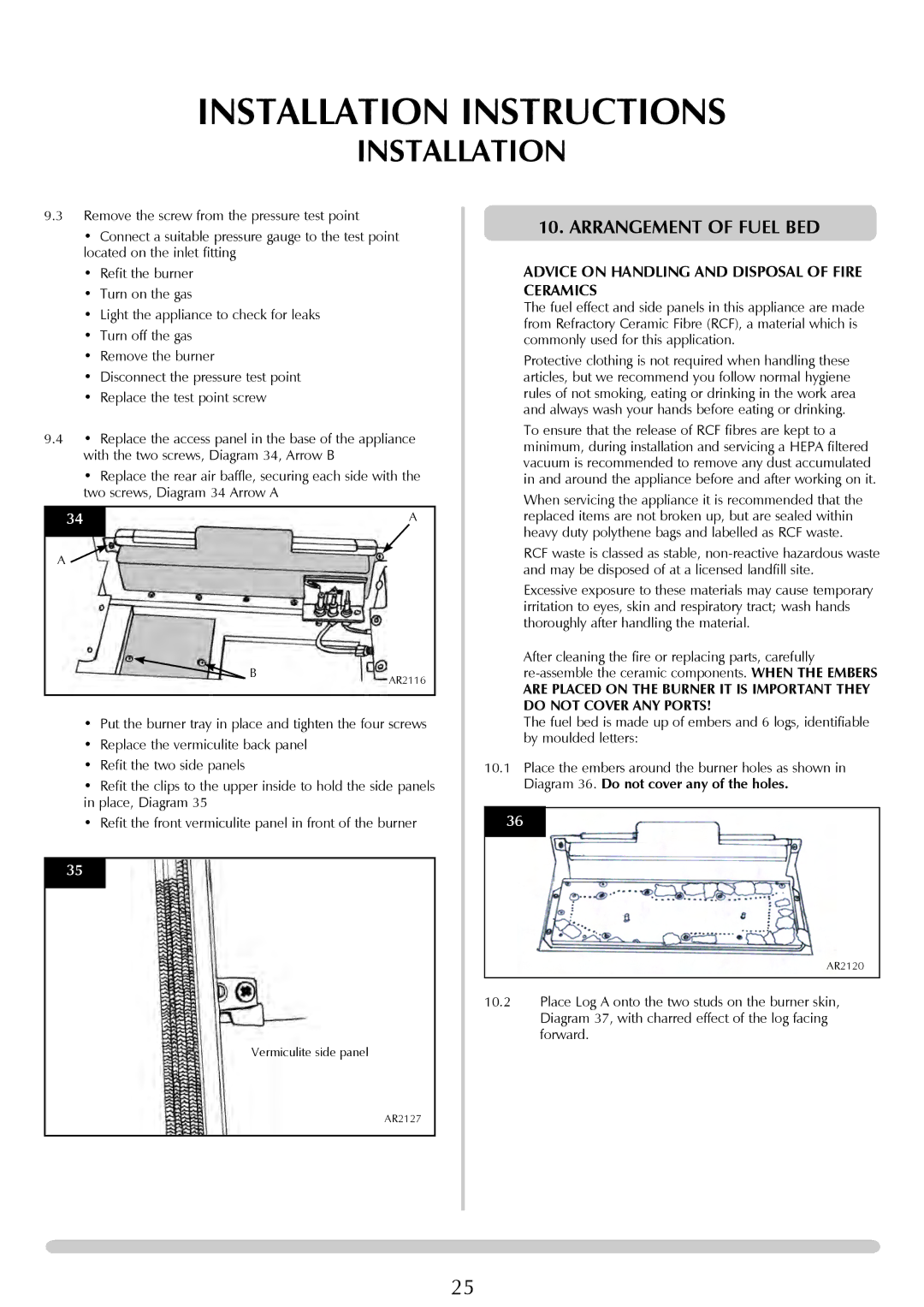
9.4• Replace the access panel in the base of the appliance with the two screws, Diagram 34, Arrow B
•Replace the rear air baffle, securing each side with the two screws, Diagram 34 Arrow A
34 | A |
|
|
A ![]()
B | AR2116 |
|
•Put the burner tray in place and tighten the four screws
•Replace the vermiculite back panel
•Refit the two side panels
•Refit the clips to the upper inside to hold the side panels in place, Diagram 35
•Refit the front vermiculite panel in front of the burner
35
Vermiculite side panel
10. ARRANGEMENT OF FUEL BED
ADVICE ON HANDLING AND DISPOSAL OF FIRE CERAMICS
The fuel effect and side panels in this appliance are made from Refractory Ceramic Fibre (RCF), a material which is commonly used for this application.
Protective clothing is not required when handling these articles, but we recommend you follow normal hygiene rules of not smoking, eating or drinking in the work area and always wash your hands before eating or drinking.
To ensure that the release of RCF fibres are kept to a minimum, during installation and servicing a HEPA filtered vacuum is recommended to remove any dust accumulated in and around the appliance before and after working on it.
When servicing the appliance it is recommended that the replaced items are not broken up, but are sealed within heavy duty polythene bags and labelled as RCF waste.
RCF waste is classed as stable,
Excessive exposure to these materials may cause temporary irritation to eyes, skin and respiratory tract; wash hands thoroughly after handling the material.
After cleaning the fire or replacing parts, carefully
ARE PLACED ON THE BURNER IT IS IMPORTANT THEY DO NOT COVER ANY PORTS!
The fuel bed is made up of embers and 6 logs, identifiable by moulded letters:
10.1Place the embers around the burner holes as shown in Diagram 36. Do not cover any of the holes.
36
AR2120
10.2Place Log A onto the two studs on the burner skin,
Diagram 37, with charred effect of the log facing forward.
AR2127
25