
EH12-2, EH17-2, EH25-2 specifications
Subaru Robin Power Products has established a reputation for quality and reliability in the world of small engines, especially with their EH Series engines: EH12-2, EH17-2, and EH25-2. Each of these models brings unique benefits and advanced technologies, catering to various applications for both commercial and personal use.The EH12-2 is a compact engine designed for lightweight applications. Weighing in at just 66 pounds, it is ideal for portable equipment and general-purpose applications. Its 4-stroke design allows for lower emissions and greater fuel efficiency compared to traditional 2-stroke engines. The EH12-2 features a low-profile design that enhances stability while operating. Its overhead cam design enables better performance at higher RPMs, making it ideal for tasks that require consistent power and reliability.
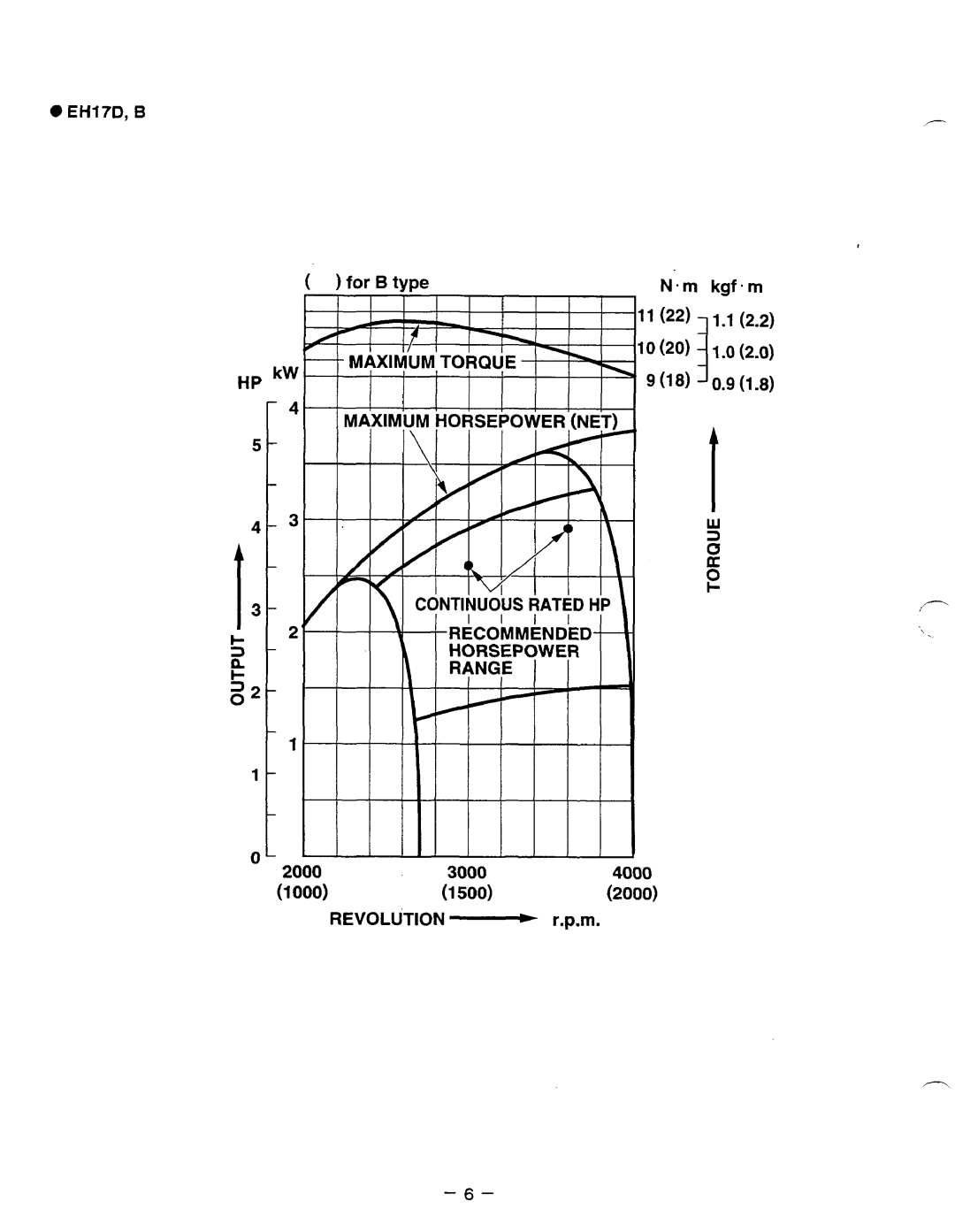
Moving up in size, the EH17-2 boasts a more robust configuration, making it suitable for semi-professional applications. With a displacement of 169cc, this engine provides higher torque and improved performance for heavier machinery. The EH17-2 also incorporates Subaru’s advanced air filtration technology, which extends engine life and reduces maintenance frequency. This engine is particularly suited for applications such as generators, pressure washers, and other equipment requiring sustained power output.
Finally, the EH25-2 stands as the powerhouse of the series. With a displacement of 252cc, it delivers exceptional torque and horsepower for demanding tasks. The EH25-2 employs Subaru's patented electronic ignition system, offering easy starts and consistent performance in a range of conditions. Its multi-point lubrication system ensures that all engine parts receive adequate oil, resulting in reduced wear and tear over time. Additionally, the EH25-2's rugged construction is designed to withstand vibration and strain, making it ideal for construction and heavy-duty industrial applications.
All three engines share core features such as a user-friendly design, efficient fuel consumption, and compliance with environmental regulations. The engines are also equipped with easy-access maintenance points, helping users perform necessary upkeep without hassle. Whether for a homeowner with occasional needs or a contractor relying on dependable machinery, Subaru's EH series provides powerful and efficient solutions tailored to meet varying demands. With their focus on innovation and quality, Subaru Robin Power Products continues to evolve and improve, ensuring their engines serve diverse markets effectively.