RGV2800, RGV4100, RGV6100 Generators
Contents
Troubleshooting
Disassembly and Assembly
Wiring Diagram
Specifcations Generator Trouble Shooting
Engine
Specifications
Model
RGV2800 RGV4100
EH34D
RGV6100
250 125 240 120 230 115 220 110 230V/115V Load Rated
Perfomance Curves
DC Output
Features
LONG-LIFE Durability
Minimal Maintenance
External View
General Description
OIL Drain Plug
RGV2800 U.S.A., 60Hz-120V Nema Receptacle
Control Panel
RGV4100 U.S.A., 60Hz-120V/240V Nema Receptacle
RGV6100 U.S.A., 60Hz-120V/240V Nema Receptacle
Location of Serial Number and Specification Number
Construction
Construction and Function
Function
Stator
Rotor
Condenser
DC Circuit Breaker
NO-FUSE Breaker
Object or Protection
RGV2800
AC plug Description
Style Ampere
Connecting to Domestic Circuits House Wiring
240V appliance
Generation of NO-LOAD Voltage
Generator Operation
Voltage Fluctuations Under Load
Switch
Full Power Switch Dual Voltage Type
Position
120/240 Half of rated output Rated output
Page
Description
Power supply
Principle of Sensing OIL Level
HOW IT Operates
Judgement of oil level
Block Diagram of the Circuit
Decision of oil shortage
Automatic stop of engine
Page
Do not connect the generator to the commercial power lines
Safety Precautions
Do not place inflammable materials near the generator
Operate the generator on a level surface
Mercury lamps with a smaller power factor
Incandescent lamp, heater, etc. with a power factor
Range of Applications
RGV2800 RGV4100 RGV6100
Appliances without any indication as to power consumption
Area / mm3 Current / a
Sectional Allowable Gauge No Resistance
10 a 12 a 15 a
Specifications
Measuring Procedures
Measuring Instruments
1 Dr. Robin Generator Tester
Voltmeter
Instruments
Circuit Tester
DC Output Measuring
AC Output Measuring
Rated voltage 120 240
Stator
Measuring Insulation Resistance
Rotor
Control Panel
Voltmeter
Checking Functional Members
AC Receptacles
Winding
Specification AC Winding Condenser
Condenser
Rotor Assembly
75 Ω 77 Ω 60 Ω
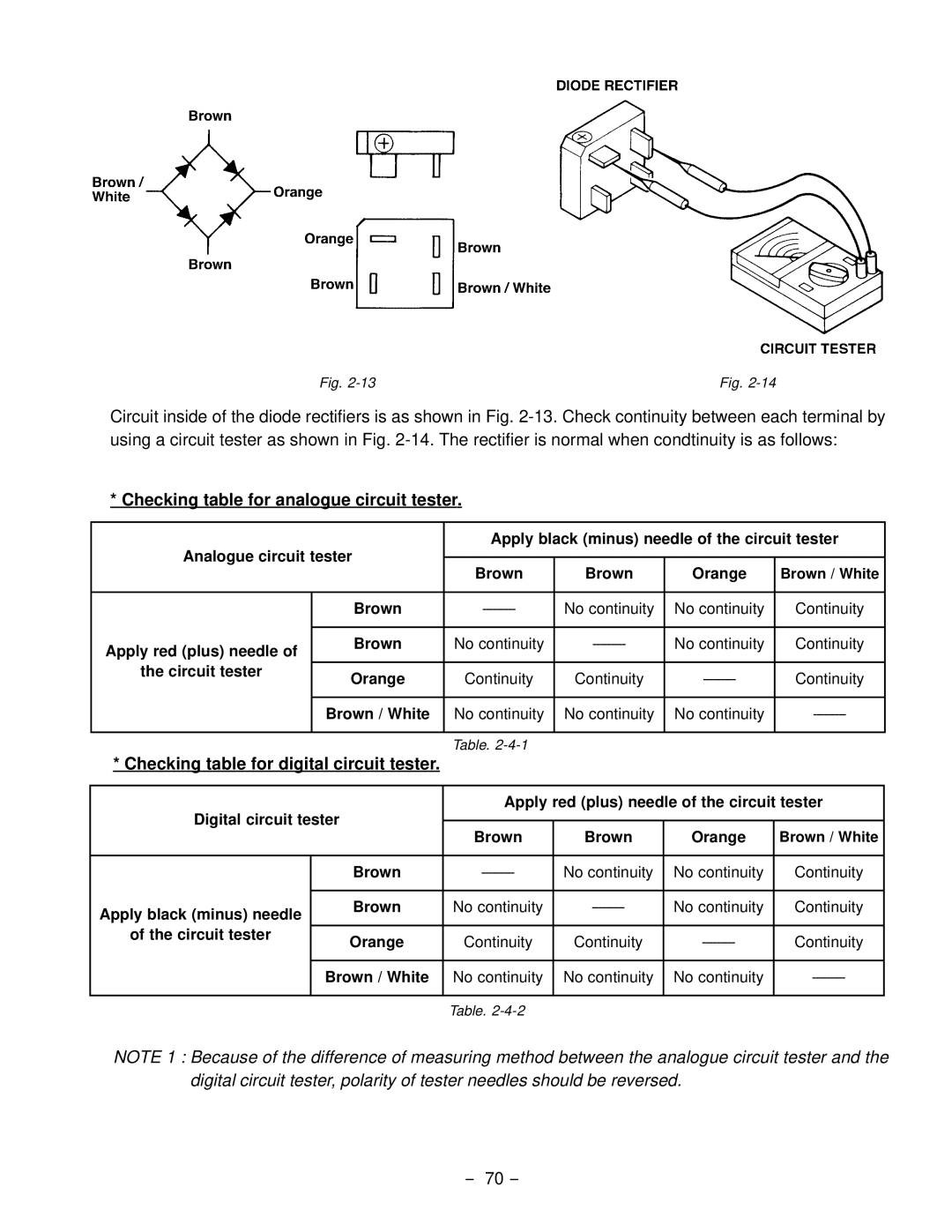
Checking table for analogue circuit tester
Diode Rectifier
Apply red plus needle Brown
Circuit tester Orange
Apply black minus needle Brown
Checking table for digital circuit tester
Circuit tester
Brown / White
Preparation and Precautions
Disassembly and Assembly
Step Part to remove Description Remarks Tool
Disassembly Procedures
Rubber Pipe Hose Clamp
Step Part to remove Description Remarks Tool
M8 flange nut pcs
Rear Cover
Stator Cover Rear Cover Brushing Spring
Seal Tape
Part to remove Description Remarks Tool
Front Cover
Assembly Procedures
Tightening torque 11.8 13.7 N-m
Tightening torque 11.3 13.2 N-m RGV2800
Tightening torque 5.9 N-m
Rear Cover
Frame
END Cover RGV4100 only
Tightening torque 21.6 27.4 N-m
Tightening torque 9.8 N-m
Tightening torque 18.6 24.5 N-m
Tightening torque 6.9 N-m
Front Panel
Disassembly
Checking of the Front Panel
Tightening torque 1.5 N-m
Reassembly
No AC Output
Troubleshooting
Checking Condenser
Checking Stator
Remedy
Checking Rotor
AC Voltage is TOO High or TOO LOW
How to adjust engine r.p.m
Checking Engine Speed
Checking Rotor
Check the Appliance for Trouble
Check the Engine Speed
Check if the Engine is Overheated
Check the Insulation of the Generator
No DC Output
Idle Control
Engine Speed is not Increased When a Load is Applied
Check the DC Coil
Dual Voltage Type
Single Voltage Type
Apply red plus needle
Normal Resistance
Engine Speed is not Reduced When Load is OFF
RGV2800 U.S.A., 60Hz-120V Type Nema Receptacle
Wiring Diagram
RGV4100 U.S.A., 60Hz-120V/240V Type Nema Receptacle
Generator
RGV6100 U.S.A., 50Hz-120V/240V Type Nema Receptacle
RGV4100, 6100 Electric Starter Type
Wiring color cord
OdelM
RGV4101RGV6101
RGV4101 RGV6101
Generator Troubleshooting
RGV4101
85 Ω
RGV4101 RGV6101
Check the Engine Speed
No DC Output
Checking table for analogue circuit tester
Idle Control Optional Equipment
Idelcontrolunit Output Wire ZCT
TheIDELCONTROLUNIT
Range of Applications
Appliances without any indication as to power consumption
Sectional Allowable Gauge No Resistance
RGV4101 Electric starter model
RGV4101
RGV6101 Electric starter model
RGV6101
Lively Blvd. Wood Dale, IL 60191 Phone 630-350-8200 Fax