2 ![]()
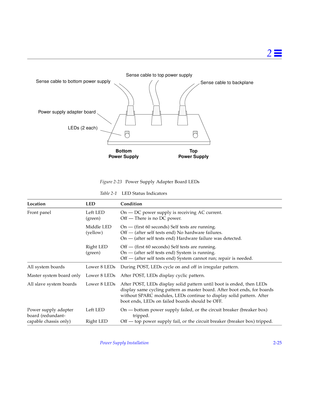
| Sense cable to top power supply |
Sense cable to bottom power supply | Sense cable to backplane |
Power supply adapter board
LEDs (2 each)
Bottom | Top |
Power Supply | Power Supply |
Figure 2-23 Power Supply Adapter Board LEDs
Table 2-1 LED Status Indicators
Location | LED | Condition |
Front panel | Left LED | On — DC power supply is receiving AC current. |
| (green) | Off — There is no DC power. |
| Middle LED | On — (first 60 seconds) Self tests are running. |
| (yellow) | Off — (after self tests end) No hardware failures. |
|
| On — (after self tests end) Hardware failure was detected. |
| Right LED | Off — (first 60 seconds) Self tests are running. |
| (green) | On — (after self tests end) System is running. |
|
| Off — (after self tests end) System cannot run; repair is needed. |
|
|
|
All system boards | Lower 8 LEDs | During POST, LEDs cycle on and off in irregular pattern. |
Master system board only | Lower 8 LEDs | After POST, LEDs display cyclic pattern. |
All slave system boards | Lower 8 LEDs | After POST, LEDs display solid pattern until boot is ended, then LEDs |
|
| display same cycling pattern as master board. After boot ends, for boards |
|
| without SPARC modules, LEDs continue to display solid pattern. After |
|
| boot ends, LEDs on failed boards should be OFF. |
Power supply adapter | Left LED | On — bottom power supply failed, or the circuit breaker (breaker box) |
board (redundant- |
| tripped. |
capable chassis only) | Right LED | Off — top power supply fail, or the circuit breaker (breaker box) tripped. |
|
|
|
Power Supply Installation |