![]() 2
2
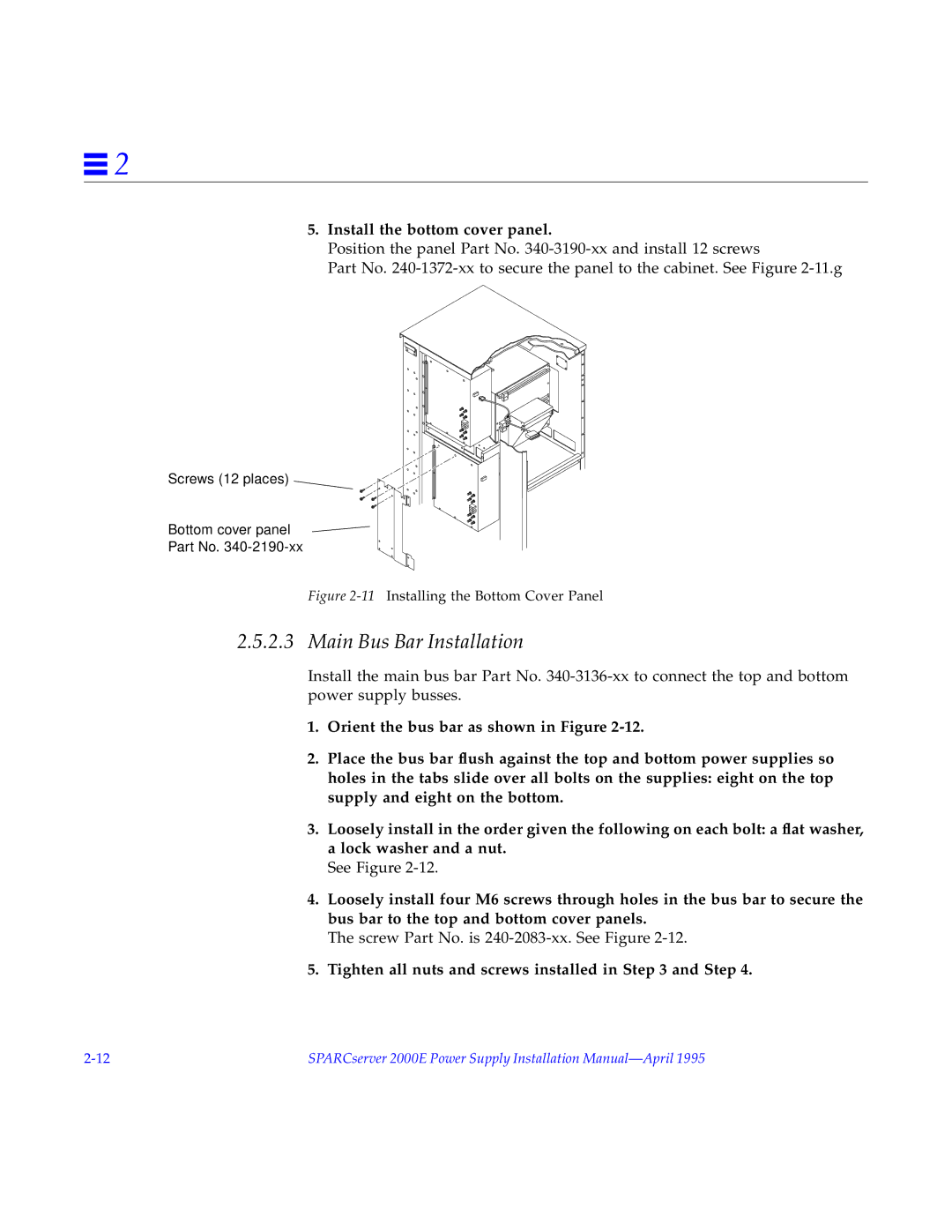
5.Install the bottom cover panel.
Position the panel Part No.
Part No.
Screws (12 places)
Bottom cover panel
Part No.
Figure 2-11 Installing the Bottom Cover Panel
2.5.2.3 Main Bus Bar Installation
Install the main bus bar Part No.
1.Orient the bus bar as shown in Figure
2.Place the bus bar flush against the top and bottom power supplies so holes in the tabs slide over all bolts on the supplies: eight on the top supply and eight on the bottom.
3.Loosely install in the order given the following on each bolt: a flat washer, a lock washer and a nut.
See Figure
4.Loosely install four M6 screws through holes in the bus bar to secure the bus bar to the top and bottom cover panels.
The screw Part No. is
5.Tighten all nuts and screws installed in Step 3 and Step 4.
SPARCserver 2000E Power Supply Installation |