Sun Microsystems, Inc
Sun Enterprise 220R Server Owner’s Guide
Please Recycle
FCC Class A Notice
Regulatory Compliance Statements
DOC Class A Notice - Avis DOC, Classe A
iv Sun Enterprise 220R Server Owner’s Guide October
BSMI Class A Notice
USA-FCC Class A
Safety
Declaration of Conformity
Supplementary Information
vi Sun Enterprise 220R Server Owner’s Guide October
Placement of a Sun Product
Safety Agency Compliance Statements
Safety Precautions
Symbols
System Unit Cover
Power Cord Connection
Lithium Battery
Battery Pack
Sicherheitsvorkehrungen
Symbole
Einhaltung sicherheitsbehördlicher Vorschriften
CD-ROM
Gehäuseabdeckung
Anschluß des Netzkabels
Lithiumbatterie
Batterien
Modification du matériel
Symboles
Conformité aux normes de sécurité
Mesures de sécurité
Batterie au lithium
Positionnement d’un produit Sun
Conformité SELV
Connexion du cordon d’alimentation
Conformité aux certifications Laser
Normativas de seguridad
Bloc-batterie
Couvercle
Conexión del cable de alimentación eléctrica
Cumplimiento de la normativa SELV
Modificaciones en el equipo
Ubicación de un producto Sun
Paquete de pilas
GOST-R Certification Mark Nordic Lithium Battery Cautions
Aviso de cumplimiento con requisitos de láser
Batería de litio
xvi Sun Enterprise 220R Server Owner’s Guide October
Sverige
Danmark
Suomi
Regulatory Compliance Statements Declaration of Conformity
Contents
Safety Agency Compliance Statements Preface
2. System Setup
4. Hardware Configuration
3. Administration and Network Setup
Contents
xx Sun Enterprise 220R Server Owner’s Guide October
6. Using Storage Devices
7. Diagnostics and Troubleshooting
5. Replacing a Disk Drive
B. System Specifications Index
A. Connector Signal Descriptions
xxii Sun Enterprise 220R Server Owner’s Guide October
Preface
xxiv Sun Enterprise 220R Server Owner’s Guide October
How This Book Is Organized
Typographic and Command Entry Conventions
Using UNIX Commands
Solaris Handbook for Sun Peripherals
Related Documentation
Shell Prompts
docfeedback@sun.com
Accessing Sun Documentation Online
Sun Welcomes Your Comments
http//docs.sun.com
xxviii Sun Enterprise 220R Server Owner’s Guide October
About the Sun Enterprise 220R Server
System Overview
2 Sun Enterprise 220R Server Owner’s Guide October
Error-correcting code ECC on memory and all data paths
optional Tape drive
Locating Front Panel Features
Keyswitch
CD-ROM or
page
screw hole
Locating Back Panel Features
6 Sun Enterprise 220R Server Owner’s Guide October
LED indicators Power button Power On/Off position Keyswitch
About the Status and Control Panel
Locked position Standby position
Keyswitch Settings
Power-on/ Activity General fault
System LED Indicators
This green LED lights continuously when the system power is on
10 Sun Enterprise 220R Server Owner’s Guide October
System Setup
Tools Required for Setup and Rackmounting
Using the Setup and Rackmounting Guide
About the Parts Shipped to You
Before You Begin
How to Install the Sun Enterprise 220R Server
What to Do
3. Install the system into the rack
2. Install any optional drive shipped with your system
Note -Each outlet must connect the system to a 15A circuit for North America and Japan, and to a 10A circuit for Europe. See your local electrical codes
9. Install and boot the operating system software
6. Set up a console for your server
7. Configure the network interface
8. Turn on power to your server
11. Load additional software from the server media kit
About Server Rackmounting
First
Holes 99, 100, or Holes 27, 28, or Holes 15, 16, or Holes 3, 4, or
Ninth
Third
How to Remove the System From the Rack
2. Locate the flat spring catch shown in the following figure
7. Reattach, close, and lock the rack doors as appropriate
What Next
3. Prepare to remove the system
5. Set the system on a workbench or other stable surface
How to Place the System Into the Rack
3. Lift the system
1. Extend the cabinet’s anti-tip legs
24 Sun Enterprise 220R Server Owner’s Guide October
5. Insert the system glides into the inner slides of the rack glides
26 Sun Enterprise 220R Server Owner’s Guide October
10. Reattach, close, and lock the rack doors as appropriate
About Communicating With the Server
How to Attach an Alphanumeric ASCII Terminal
3. Set the terminal to receive
2. Connect the terminal’s power cable to an AC outlet
1. Install the graphics card into a vacant PCI slot
How to Configure a Local Graphics Console
32 Sun Enterprise 220R Server Owner’s Guide October
3. Connect the monitor’s power cord to an appropriate AC power outlet
4. Connect the keyboard cable to the server’s keyboard/mouse port
1. Turn on power to any peripherals and external storage devices
How to Power On the System
2. Turn on power to the monitor or terminal
4. Press the front panel Power button once
3. Turn the front panel keyswitch to the Power-On/Off position
Power-On/Off position Power button
Locked position
5. Turn the keyswitch to the Locked position
36 Sun Enterprise 220R Server Owner’s Guide October
How to Install the System Software
Installing the Operating System From CD-ROM
Solaris 2.6 Hardware 5/98 Installation Requirement
Installing the Operating System From a Network Boot Server
Solaris 7 Software Installation
40 Sun Enterprise 220R Server Owner’s Guide October
How to Select the Boot Device
1. At the ok prompt, type
2. To reboot the system from the new boot device, type
42 Sun Enterprise 220R Server Owner’s Guide October
2. Back up the system files and data, if necessary
How to Power Off the System
1. Notify users that the system will be powered down
3. Halt the operating system using the appropriate commands
44 Sun Enterprise 220R Server Owner’s Guide October
Administration and Network Setup
About Network Interface Options
2. Determine the IP address for the interface
How to Configure the Standard Ethernet Interface
3. Resume the installation of the system
1. Assign a host name to the machine
48 Sun Enterprise 220R Server Owner’s Guide October
1. Assign a network host name to the interface
How to Add an Ethernet Interface
zardoz # cat /etc/hostname.hme1
3. Boot the operating system and log on to the system as superuser
4. Create an appropriate /etc/hostname file for the new interface
zardoz # cat /etc/hostname.hme0
zardoz # reboot -- -r
7. Reboot the system type
zardoz # cat /etc/hosts
1. Locate the RJ-45 connector for the appropriate Ethernet interface
How to Attach a Twisted-Pair Ethernet TPE Cable
What Next
1. Locate the appropriate MII Ethernet connector
How to Attach an MII Ethernet Transceiver
4. Lock the AUI connector
56 Sun Enterprise 220R Server Owner’s Guide October
At the ok prompt, type either of the two following commands
How to Boot the System Using the Standard Ethernet Interface
58 Sun Enterprise 220R Server Owner’s Guide October
ok boot net - install
pci@1f,4000/pci@5/SUNW,hme@0,1
How to Boot the System Using a PCI-Based Ethernet Interface
60 Sun Enterprise 220R Server Owner’s Guide October
2. Change the default net device. At the ok prompt, type
Hardware Configuration
Error Correction and Parity Checking
About Reliability, Availability, and Serviceability Features
Hot-Pluggable Disk Drives
Status LEDs
64 Sun Enterprise 220R Server Owner’s Guide October
Power Supply Redundancy
Hot-Swappable Power Supplies
Four Levels of Diagnostics
At the application level, you have access to SunVTS diagnostics. Like OBDiag, SunVTS provides a comprehensive test of the system, including its external interfaces. SunVTS also allows you to run tests remotely over a network connection. You can only use SunVTS if the operating system is running. For more information about SunVTS, see “About SunVTS Software” on page 132, “How to Use SunVTS Software” on page 135, and “How to Check Whether SunVTS Software Is Installed” on page
About Memory
Configuration Rules
About CPU Modules
About Peripheral Component Interconnect PCI Buses
Clock
About Disk Array Configurations and Concepts
Disk Mirroring RAID
Disk Concatenation
72 Sun Enterprise 220R Server Owner’s Guide October
Disk Striping RAID
Disk Striping With Parity RAID
Hot Spares
For More Information
Hot Plug
disk bays
About Internal Disk Drives
Disk drive LEDs
Internal
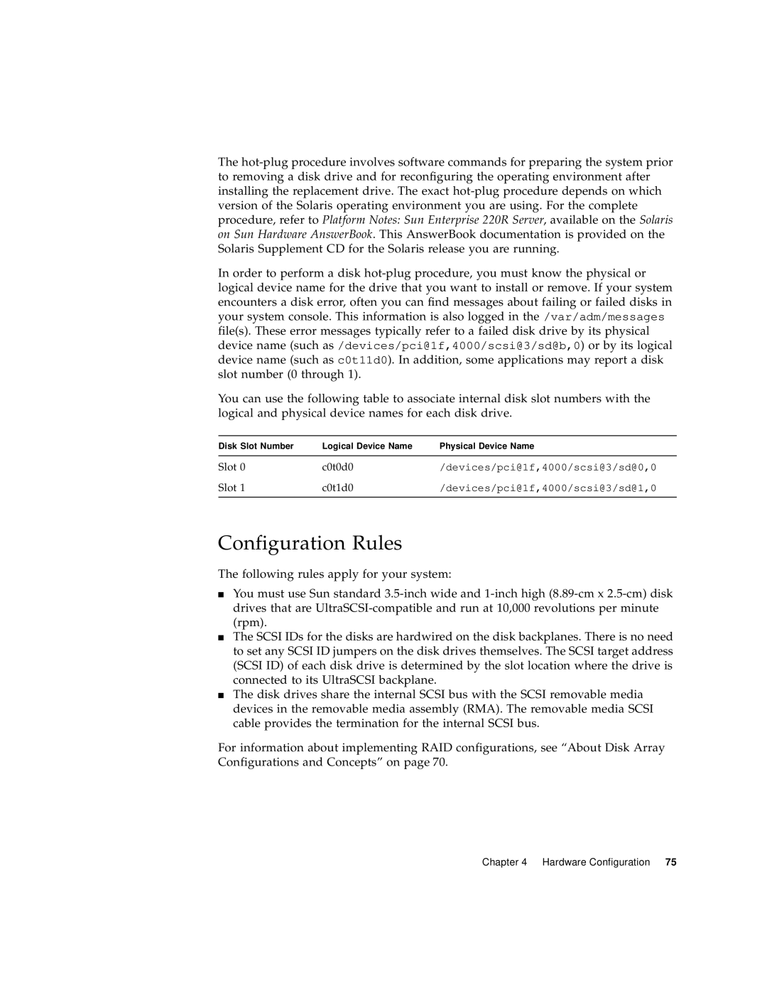
Logical Device Name
devices/pci@1f,4000/scsi@3/sd@0,0
devices/pci@1f,4000/scsi@3/sd@1,0
Disk Slot Number
About Power Supplies
Page
78 Sun Enterprise 220R Server Owner’s Guide October
About the Standard Ethernet Port
About the Serial Ports
80 Sun Enterprise 220R Server Owner’s Guide October
About the Parallel Port
About the Main Logic Board Jumpers
82 Sun Enterprise 220R Server Owner’s Guide October
About Serial Port Jumpers
About Flash PROM Jumpers
Target Devices
About the External SCSI Port
Bus Length
External SCSI Cabling and Termination
The following figures provide a summary of the cabling guidelines
Multi-initiator Support
Chapter 4 Hardware Configuration
88 Sun Enterprise 220R Server Owner’s Guide October
Replacing a Disk Drive
How to Avoid Electrostatic Discharge
3. Use an antistatic wrist strap
2. Use an antistatic mat or similar surface
1. Prepare the system for disk removal
How to Remove a Disk Drive
3. Unlock the front doors and swing them open
7. Place the disk drive on an antistatic mat
8. Repeat the procedure for the other drive if necessary
6. Holding the disk drive by the handle, slide it out of the drive bay
94 Sun Enterprise 220R Server Owner’s Guide October
1. Prepare the system to receive the new disk drive
How to Install a Disk Drive
4. Release the drive handle on the disk drive
5. Align the disk drive to its drive bay
11. Close and then lock the system front doors
10. Repeat the procedure for the other drive if necessary
2. Turn on power to the monitor or terminal, and open your console
How to Initiate a Reconfiguration Boot
ok boot -r
5. When the ok prompt is displayed, type the following command
100 Sun Enterprise 220R Server Owner’s Guide October
Using Storage Devices
2. Place a CD into the drive tray, label side up
How to Insert a Compact Disc Into the Drive
3. Gently push the tray back into the drive
Manually see “How to Eject a Compact Disc Manually” on page
1. Kill processes accessing the CD-ROM drive, if necessary
How to Eject a Compact Disc With Software Commands
2. From the console device, type
You can also eject a compact disc by using one of these methods
2. Press the Eject button on the front panel
How to Eject a Compact Disc Manually
106 Sun Enterprise 220R Server Owner’s Guide October
What Next
1. Turn off the power to your system
How to Eject a Compact Disc in an Emergency
2. Unfold and straighten one end of a large wire paper clip
What Next
Handling and Storing Tape Cartridges
About the Tape Drive and Tape Cartridges
Thermal Conditioning
2. Insert the cartridge into the drive, label side up
How to Insert a Tape Cartridge
3. Push gently on the cartridge until it is pulled into the drive
112 Sun Enterprise 220R Server Owner’s Guide October
1. Check that there is no drive activity
How to Remove a Tape Cartridge
2. Push the Eject button and remove the tape cartridge
114 Sun Enterprise 220R Server Owner’s Guide October
How to Control the Tape Drive
Insert a cleaning cartridge into the drive
How to Clean the Tape Drive
1. Clean the disc with compressed air
How to Clean a Compact Disc
Diagnostics and Troubleshooting
About Diagnostic Tools
Run POST no POST failure ?
System yes boots ? yes Fault LED lit ?
disk problem
Chapter 7 Diagnostics and Troubleshooting
About Power-On Self-Test POST Diagnostics
Setting Up a tip Connection
How to Use POST Diagnostics
4. In a shell window on the Sun system, type
3. To use serial port A
a. Copy and paste the serial port B remote file
b. Modify the serial port B system remote file as follows
Verifying the Baud Rate
5. When POST is completed, disconnect the tip window as follows
c. Type the following to kill the tip hardwire process
3. Verify the following serial port default settings as follows
Results
1. When the ok prompt is displayed, type the following command
Observing POST in Progress
If a Sun Type-5 keyboard is attached to the system, POST status and error indications are also displayed via the four LEDs on the keyboard. When POST starts, all four keyboard LEDs blink on and off simultaneously. After that, the Caps Lock LED blinks slowly to indicate POST is running. If an error is detected, the pattern of the lit LEDs provides an error indication. See “Error Indications” on page 138 for more information
About OpenBoot Diagnostics OBDiag
OBDiag Menu
OBDiag Configuration Variable Settings
2. Optional Select a diagnostic level
How to Use OpenBoot Diagnostics OBDiag
3. Then type
The OBDiag Test menu is displayed
4. At the ok prompt, type
5. At the ok prompt, type
The OBDiag menu is displayed
2. To set the diag-level variable, type the following
How to Set the Diagnostic Level for POST and OBDiag
About SunVTS Software
SunVTS Test Reference Manual
SunVTS User’s Guide
SunVTS Quick Reference Card
1. Type the following
How to Check Whether SunVTS Software Is Installed
2. Remotely log in to the server as superuser or root
How to Use SunVTS Software
3. Check whether SunVTS software is loaded on the server
# cd /opt/SUNWvts/bin # ./sunvts -display localhostname0
4. To start the SunVTS software, type
About Sun Enterprise SyMON Software
Error Indications
About Troubleshooting Your System
Front Panel LEDs
Scroll Lock
Keyboard LEDs
Stop
D key
The following table provides error code definitions
The following table provides a description of each LED
Power Supply LEDs
Disk LEDs
Error Messages
Internal disk drive LEDs
Solaris prtdiag Command
Software Commands
ok /usr/platform/sun4u/sbin/prtdiag
prtdiag output
OBP printenv Command
OBP show-devs Command
OBP probe-scsi and probe-scsi-all Commands
ok probe-scsi
probe-scsi output
probe-scsi-all output
ok probe-scsi
Action
About Diagnosing Specific Problems
Symptom
Network Communications Failure
Determining the Device Name of the Ethernet Interface
Solution
3. Reboot the system to make the changes effective
4. Reboot the system to make the changes effective
Video Output Failure
Power-On Failure
1. Run POST diagnostics
4. If the POST output contains an error message, then POST has failed
Replace the drive indicated by the failure message
Disk or CD-ROM Drive Failure
1. At the system ok prompt, type
2. If a disk doesn’t respond, replace the unresponsive drive
SCSI Controller Failure
DIMM Failure
Power Supply Failure
152 Sun Enterprise 220R Server Owner’s Guide October
Page
154 Sun Enterprise 220R Server Owner’s Guide October
Connector Signal Descriptions
Keyboard/Mouse Connector Diagram
Reference for the Keyboard/Mouse Connector
Keyboard/Mouse Connector Signals
Serial Port A and B Connector Diagram
Reference for the Serial Port A and B Connectors
Serial Port Signals
158 Sun Enterprise 220R Server Owner’s Guide October
Not connected
TPE Connector Diagram
Reference for the Twisted-Pair Ethernet TPE Connector
TPE Connector Signals
UltraSCSI Connector Diagram
Reference for the UltraSCSI Connector
UltraSCSI Connector Signals
162 Sun Enterprise 220R Server Owner’s Guide October
Dat13
164 Sun Enterprise 220R Server Owner’s Guide October
Parallel Port Connector Diagram
Reference for the Parallel Port Connector
166 Sun Enterprise 220R Server Owner’s Guide October
Signal ground
120 2140
Reference for the Media Independent Interface MII Connector
MII Connector Diagram
MII Connector Signals
Txclk
170 Sun Enterprise 220R Server Owner’s Guide October
36GndGround 37GndGround 38GndGround 39GndGround 40PwrPower
A P P E N D I X B
System Specifications
“Physical Specifications” on page “Electrical Specifications” on page
“System Specifications” on page
Physical Specifications
Reference for System Specifications
Electrical Specifications
The environmental requirements for the system are as follows
Environmental Specifications
174 Sun Enterprise 220R Server Owner’s Guide October
Index
Page
Page
See also Ethernet ATM
diag-switch?, 121, 129 operating system software
Page
watch-net-all command