SUPERSERVER
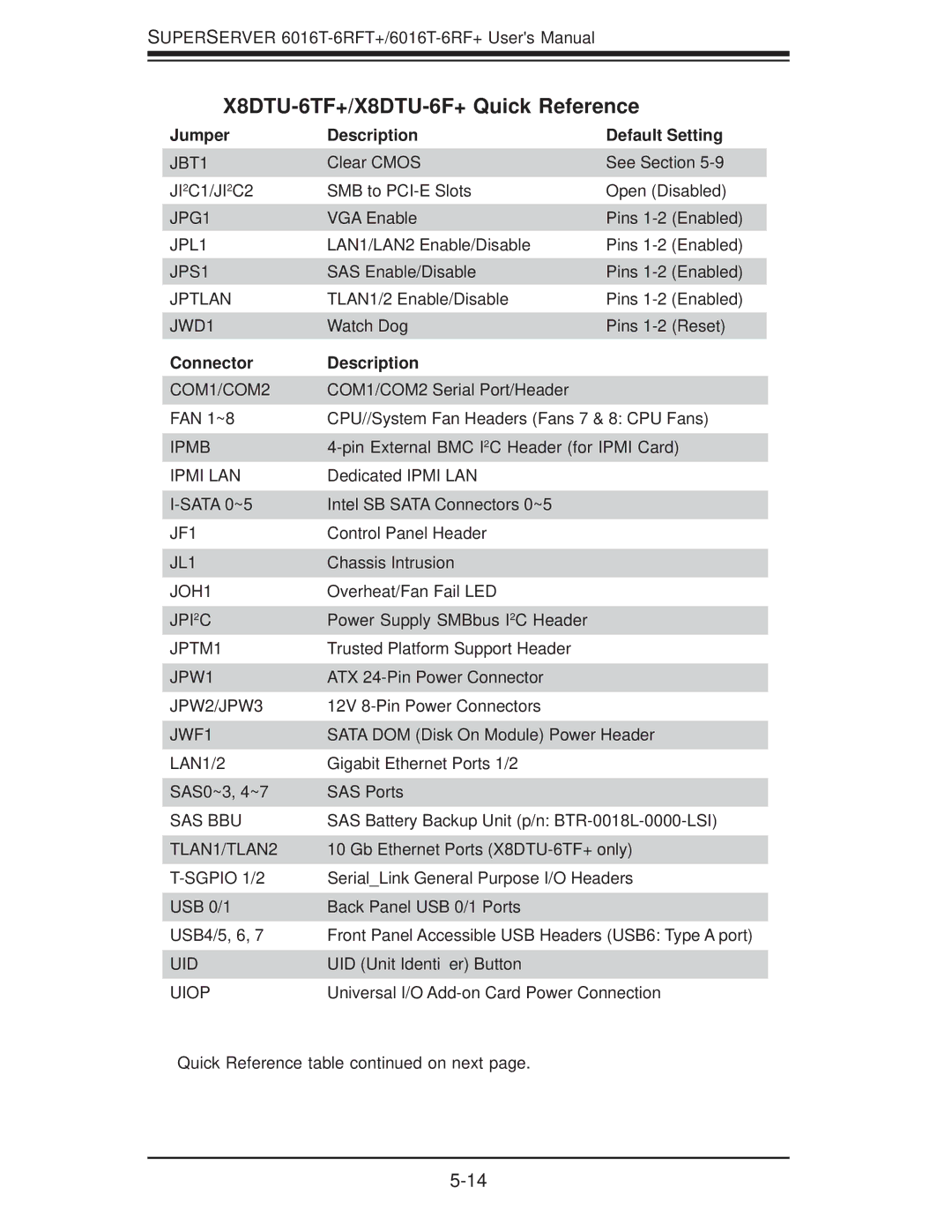
X8DTU-6TF+/X8DTU-6F+ Quick Reference
Jumper | Description | Default Setting | |
JBT1 | Clear CMOS | See Section | |
JI2C1/JI2C2 | SMB to | Open (Disabled) | |
JPG1 | VGA Enable | Pins | |
JPL1 | LAN1/LAN2 Enable/Disable | Pins | (Enabled) |
JPS1 | SAS Enable/Disable | Pins | (Enabled) |
JPTLAN | TLAN1/2 Enable/Disable | Pins | (Enabled) |
JWD1 | Watch Dog | Pins | (Reset) |
Connector | Description |
COM1/COM2 | COM1/COM2 Serial Port/Header |
FAN 1~8 | CPU//System Fan Headers (Fans 7 & 8: CPU Fans) |
IPMB | |
IPMI LAN | Dedicated IPMI LAN |
Intel SB SATA Connectors 0~5 | |
JF1 | Control Panel Header |
JL1 | Chassis Intrusion |
JOH1 | Overheat/Fan Fail LED |
JPI2C | Power Supply SMBbus I2C Header |
JPTM1 | Trusted Platform Support Header |
JPW1 | ATX |
JPW2/JPW3 | 12V |
JWF1 | SATA DOM (Disk On Module) Power Header |
LAN1/2 | Gigabit Ethernet Ports 1/2 |
SAS0~3, 4~7 | SAS Ports |
SAS BBU | SAS Battery Backup Unit (p/n: |
TLAN1/TLAN2 | 10 Gb Ethernet Ports |
| Serial_Link General Purpose I/O Headers |
USB 0/1 | Back Panel USB 0/1 Ports |
USB4/5, 6, 7 | Front Panel Accessible USB Headers (USB6: Type A port) |
UID | UID (Unit Identifier) Button |
UIOP | Universal I/O |
Quick Reference table continued on next page.