Manuals
/
SUPER MICRO Computer
/
Computer Equipment
/
Network Card
SUPER MICRO Computer
6014P-TR
user manual
Super
Models:
6014P-TR
6014P-T
1
1
124
124
Download
124 pages
30.08 Kb
1
2
3
4
5
6
7
8
Install
Serr Signal Condition
Password
Recoverable Post Errors
Latency Timer
Onboard Indicators
Connecting Cables
Reset Configuration Data
Accessing the Drive Bays
Advanced Serverboard Setup
Page 1
Image 1
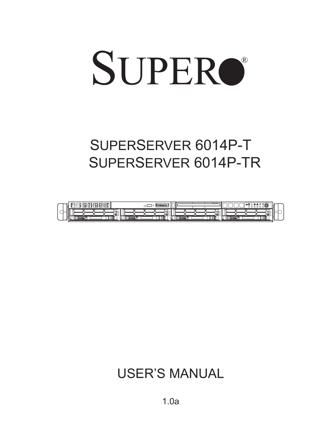
S
UPER
®
S
UPER
S
ERVER
6014P-T
S
UPER
S
ERVER
6014P-TR
USER’S MANUAL
1.0a
Page 1
Page 2
Page 1
Image 1
Page 1
Page 2
Contents
Super
Manual Revision 1.0a Release Date October 8
About This Manual
Preface
Manual Organization
Advanced Serverboard Setup
System Safety
Advanced Chassis Setup
Bios
Preface
Table of Contents
Advanced Serverboard Setup
System Safety
Bios
Advanced Chassis Setup
Appendices
Page
Overview
Chapter Introduction
Processors
Serverboard Features
Memory
Serial ATA
Other Features
Server Chassis Features
System Power
ATI Graphics Controller
Front Control Panel
PCI Expansion Slots
Backplane
Cooling System
Intel E7520 Chipset System Block Diagram
Headquarters
Contacting Supermicro
Europe
Asia-Pacific
Preparing for Setup
Chapter Server Installation
Unpacking the System
Rack Precautions
Choosing a Setup Location
Server Precautions
Rack Mounting Considerations
Installing the Inner Rails
Installing the System into a Rack
Identifying the Sections of the Rack Rails
Locking Tabs
Installing the Outer Rails
Installing the Server into a Rack
Installing the Server into the Rack
Installing the Server into a Telco Rack
Installing the Server into a Telco Rack
Checking the Serverboard Setup
Accessing the Inside of the System
Checking the Drive Bay Setup
Control Panel Buttons
Chapter System Interface
Control Panel LEDs
Serial ATA Drive Carrier LED
Page
Chapter System Safety
General Safety Precautions
ESD Precautions
Installing the Onboard Battery
Operating Precautions
Precautions
Chapter Advanced Serverboard Setup
Handling the Serverboard
Unpacking
CPU Installation
Processor and Heatsink Installation
Pin PGA Socket Empty and with Processor Installed
Heatsink Installation
Removing the Heatsink/CPU
Installing the Heatsink
Connecting Data Cables
Connecting Cables
Connecting Power Cables
JF1 Header Pins
Connecting the Control Panel
Dimm Installation Figures 5-5a and 5-5b
Installing Memory
I/O Ports
Memory Support
Memory Speed Jumpers
5a. Side View of Dimm Installation into Slot
Adding PCI Cards
PCI card installation
PCI slots
6014P-T Riser Cards Slot Add-on Card
Super X6DHP-TG Layout
Serverboard Details
Connector Description
Jumper Description Default Setting
X6DHP-TG Quick Reference
ATX Power Connector
Connector Definitions
Processor Power Connector
Power LED
NIC1/2 LEDs
Power Fail LED
Overheat/Fan Fail LED
UID Button & UID LED
Power Button
Chassis Intrusion
JLAN1/2 Ethernet Ports
Universal Serial Bus Headers
Universal Serial Bus USB0/1
Fan Headers
Serial Ports
Wake-On-Ring
Power LED/Speaker
ATX PS/2 Keyboard and PS/2 Mouse Ports
SMB
SMB Power Connector
VGA Enable/Disable
Jumper Settings
Explanation Jumpers
Cmos Clear
Sata Enable/Disable
Jlan Enable/Disable
Bios Debug
Memory Speed Select
Watch Dog
Jlan LEDs
Onboard Indicators
Unit Identifier
Floppy and Hard Disk Drive Connections
Floppy Connector
IDE Drive Connectors Pin Definitions JIDE#1, JIDE#2
IDE Connectors
Page
Static-Sensitive Devices
Chapter Advanced Chassis Setup
Tools Required
6014P-T
Control Panel
6014P-TR
System Fans
Installing a new fan
System Fan Failure
Replacing System Cooling Fans
Accessing the Drive Bays
Drive Bay Installation/Removal
Mounting a Serial ATA drive in a drive carrier
Serial ATA Drive Installation
Removing a Serial ATA Drive Carrier
Installing/removing hot-swap Sata drives
DVD/CD-ROM and Floppy Drive Installation
Power Supply Failure
Power Supply
Removing/Replacing the Power Supply
6014P-TR
6014P-T
Reconfiguring the 6014P-T see Figure
Reconfiguring the Power Supply
Reconfiguring the 6014P-TR see Figure
Page
Reconfiguring the Power Supply
Page
Chapter
Starting the Setup Utility
Introduction
Main Bios Setup
Running Setup
Press the Delete key to enter Setup
Main Setup Features
Main Bios Setup Menu
Bios Date
System Time
Native Mode Operation
Serial ATA RAID Enable
Legacy Diskette a
Parallel ATA
Type
Transfer Mode
LBA Mode Control
Ultra DMA Mode
Multi-Sector Transfer
Boot Features
Advanced Setup
Quick Boot Mode
Quiet Boot
After Power Failure
Power Button Behavior
Memory Cache Cache System Bios Area
Cache Video Bios Area
Cache Base 512K-640K
Cache Base 0-512K
Cache Extended Memory
Write Back
Discrete Mtrr Allocation
Reset Configuration Data
PCI Configuration
Onboard Glan Gigabit- LAN Oprom Configure
Latency Timer
Enable Master
Large Disk Access Mode
Force Compliance Mode
Serr Signal Condition
ECC Error Type
Processor Power Management
USB Function
KBC Clock input
Device Configuration
Onboard COM1
Base I/O Address
ECC Event Logging
Event Logging
Mark DMI Events as Read
Clear All DMI Event Logs
Mode
Serial Port B
Parallel Port
Interrupt
P1V8 Vdimm
Hardware Monitor Logic CPU Temperature Threshold
User Password Is
Supervisor Password Is
Security
N12VScaled
Set User Password
Set Supervisor Password
Fixed Disk Boot Sector
Password on Boot
+Removable Devices
Boot
Cdrom Drive
+Hard Drive
Exit
Load Setup Defaults
Exit Saving Changes
Exit Discarding Changes
Save Changes
Page
Recoverable Post Errors
Appendix a Bios Post Codes
Terminal Post Errors
Post Code Description
Post Code Description
Post Code Description
Post Code Description
Following are for boot block in Flash ROM
Page
Configuring Bios settings for the Sata RAID Functions
Appendix B Software Installation
Adaptec Embedded Sata RAID Controller Driver
Serial ATA Sata
Adaptec Embedded Sata with HostRAID Controller Driver
Using the Array Configuration Utility ACU
Using the Adaptec RAID Configuration Utility ARC
Managing Arrays
From the ARC menu, select Array Configuration Utility ACU
Viewing Array Properties
Deleting Arrays
ACU
To create an array
Creating Arrays
To assign properties to the new array
Assigning Array Properties
When fi nished, press Done as shown on the following screen
Page
Deleting a Bootable Array
Adding a Bootable Array
Ctrl+B
Adding/Deleting Hotspares
To initialize drives
Initializing Disk Drives
Select Initialize Drives
Page
To Rebuild an array
Rebuilding Arrays
To access the disk utilities
Using the Disk Utilities
You can choose from the following options
To Exit Adaptec RAID Configuration Utility
Installing Intels ICH5R Driver by Adaptec and Windows OS
Installing Other Drivers
Installing Other Software Programs and Drivers
Figure B-2. Supero Doctor III Health Information Display
Supero Doctor
Figure B-3. Supero Doctor III Remote Control Display
Appendix C System Specifications
PFC Power Supply ratings apply to each module
Weight
Expansion Slots
Serverboard
Regulatory Compliance
Operating Environment
Top
Page
Image
Contents