Chapter 5: Advanced Serverboard Setup
5-4 I/O Ports
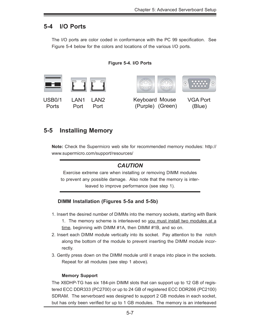
The I/O ports are color coded in conformance with the PC 99 specifi cation. See Figure
Figure 5-4. I/O Ports
5-5 Installing Memory
Note: Check the Supermicro web site for recommended memory modules: http://
www.supermicro.com/support/resources/
CAUTION
Exercise extreme care when installing or removing DIMM modules to prevent any possible damage. Also note that the memory is inter- leaved to improve performance (see step 1).
DIMM Installation (Figures 5-5a and 5-5b)
1.Insert the desired number of DIMMs into the memory sockets, starting with Bank 1. The memory scheme is interleaved so you must install two modules at a time, beginning with DIMM #1A, then DIMM #1B, and so on.
2.Insert each DIMM module vertically into its socket. Pay attention to the notch along the bottom of the module to prevent inserting the DIMM module incor- rectly.
3.Gently press down on the DIMM module until it snaps into place in the sockets. Repeat for all modules (see step 1 above).
Memory Support
The