A C T I V E S T U D I O M O N I T O R S
7.1 Digital 192kHz Set-up
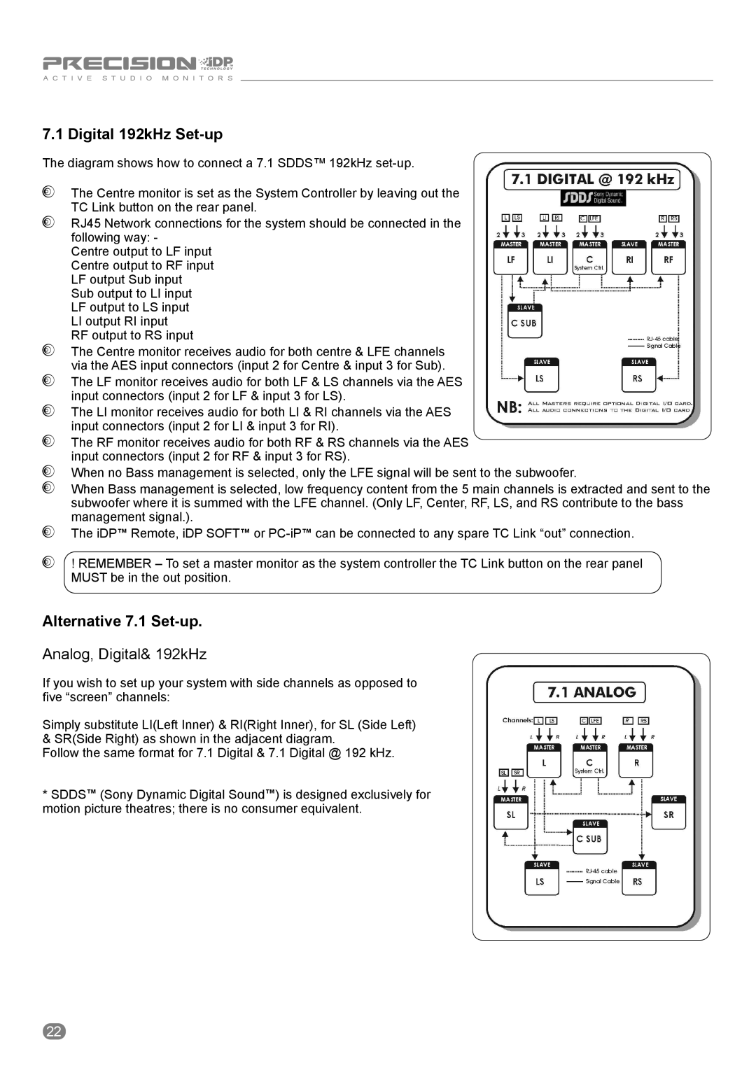
The diagram shows how to connect a 7.1 SDDS™ 192kHz
The Centre monitor is set as the System Controller by leaving out the TC Link button on the rear panel.
RJ45 Network connections for the system should be connected in the following way: -
Centre output to LF input Centre output to RF input LF output Sub input Sub output to LI input LF output to LS input
LI output RI input
RF output to RS input
The Centre monitor receives audio for both centre & LFE channels via the AES input connectors (input 2 for Centre & input 3 for Sub).
The LF monitor receives audio for both LF & LS channels via the AES input connectors (input 2 for LF & input 3 for LS).
The LI monitor receives audio for both LI & RI channels via the AES input connectors (input 2 for LI & input 3 for RI).
The RF monitor receives audio for both RF & RS channels via the AES input connectors (input 2 for RF & input 3 for RS).
When no Bass management is selected, only the LFE signal will be sent to the subwoofer.
When Bass management is selected, low frequency content from the 5 main channels is extracted and sent to the subwoofer where it is summed with the LFE channel. (Only LF, Center, RF, LS, and RS contribute to the bass management signal.).
The iDP™ Remote, iDP SOFT™ or
! REMEMBER – To set a master monitor as the system controller the TC Link button on the rear panel MUST be in the out position.
Alternative 7.1 Set-up.
Analog, Digital& 192kHz
If you wish to set up your system with side channels as opposed to five “screen” channels:
Simply substitute LI(Left Inner) & RI(Right Inner), for SL (Side Left) & SR(Side Right) as shown in the adjacent diagram.
Follow the same format for 7.1 Digital & 7.1 Digital @ 192 kHz.
*SDDS™ (Sony Dynamic Digital Sound™) is designed exclusively for motion picture theatres; there is no consumer equivalent.
22