31
Model PH90 Operating Procedures
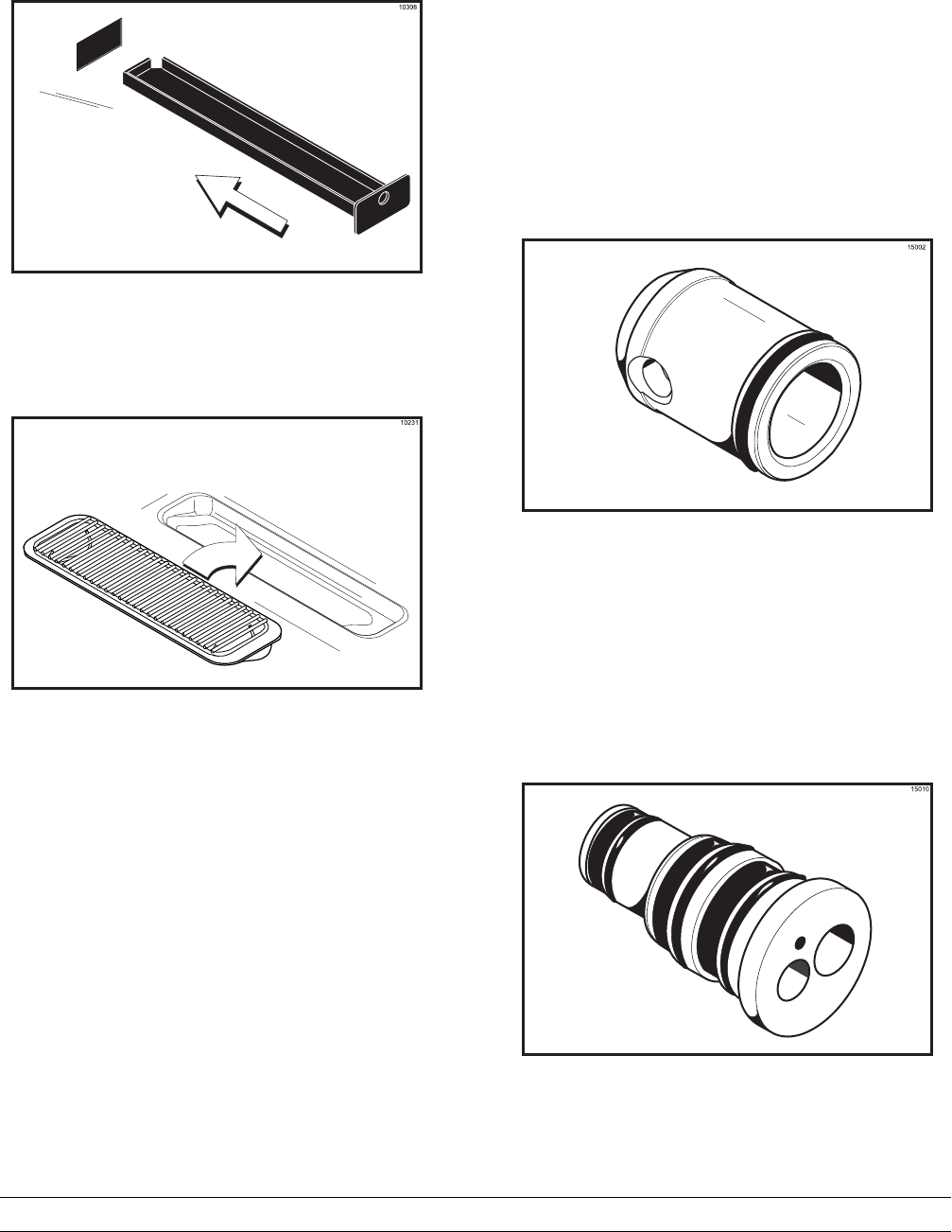
Install the two notched drip pans in the left and right
side panels. (See Figure 35.)
Figure 35
Step 8
Install the front drip tray and splash shield under the
door spouts. (See Figure 36.)
Figure 36
Mix Hopper AssemblyTo assemble the mix hopper for both sides of the
freezer, the steps will be the same. Therefore, first
assemble the shake mix hopper, then go back and
duplicate these procedures for the soft ser ve mix
hopper.
With the parts trays available:
Step 1
Inspect the rubber pump parts. The check rings and
o--ringsmust bein 100% good condit ion for the pump
and entire unit to operate properly. Check rings and
o--ringscannot properly serv e their intended functions
if nicks, cuts, or holesin the material are present. The
rubber poppet must also be in good condition.
Refer to page 75 f or the normal replacement
schedule. Replace any defective parts immediately
and discard the old.
Step 2
Assemble the piston. Slide the o --ringinto the groove
of the piston. DO NOT lubricate this o--ring. (See
Figure 37.)
Figure 37
Step 3
Assemble the valve body. Slide two large and one
small o--ring, and two large and one small check ring
into their respective grooves on the valve body. (See
Figure 38.)
Figure 38