54 Model PH90Operating Procedures
Step 4
Install the plunger insert into t he plunger tube by
positioning the end of the insert withthe beveled edge
and smaller hole to enter into the plunger tube first.
Step 5
Install the plunger nut onto the plunger tube.
Step 6
Install the knob o--ring into the groove provided in the
knob.
Step 7
Install the plunger tube assembly onto the plunger
assembly by inserting the plunger assembly into the
larger opening on the plunger tube. Push the plunger
assembly, compressing the spring, until the threaded
end of the stem projects through the smaller opening
on the plunger tube and the insert. (See Figure 115.)
Figure 115
Step 8
Install the knob with the knob o--ringonto t het hreaded
end of the plunger assembly. Hold the plunger
assembly so that the plunger tube, compressing the
spring, is pulled toward the piston end as far as it will
go. Tighten the knob by turning it clockwise.
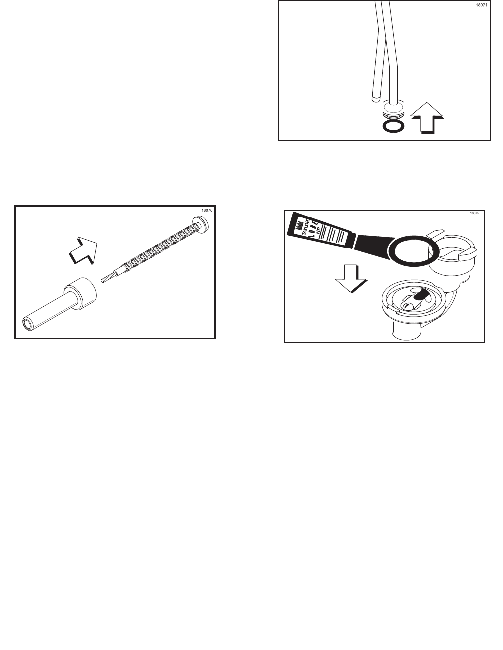
Step 9
Lubricate and install the 1” o--ring onto the groove
provided on the discharge tube. (See Figure 116.)
Figure 116
Step 10
Lubricate and install the 1--5/16” o--ring into the valve
body. (See Figure 117.)
Figure 117
Step 11
Install the discharge tube onto the smaller opening in
the valve body by aligning the flats on the discharge
tube with the locking grooves on the valve body. Push
downt he discharge tube until it is seated into thevalve
body opening. Turn the discharge tube clockwise to
fully engage it into locking grooves on the valve body.