Tiger JD 5083E manual Assembly Driveshaft Access, Adjusting Rear Wheels, Panel Bolts To Be Removed

Models: JD 5093E JD 5101E JD 5083E

1 164
Download 164 pages 50.4 Kb
Page 27
Image 27
ASSEMBLY

ASSEMBLY

DRIVESHAFT ACCESS

To access the driveshaft of the JD-5101E, a hole will need to be cut in the front of the tractor frame. Find the tapped marking on the front end of the tractor (shown below.) Using a 1-1/2” hole saw, cut a hole for the driveshaft. Once the hole is cut you will be able to look through the hole and see the driveshaft cover.

DRIVESHAFT COVER

PRE-TAPPED

MARKING

HARDWARE TO BE REMOVED

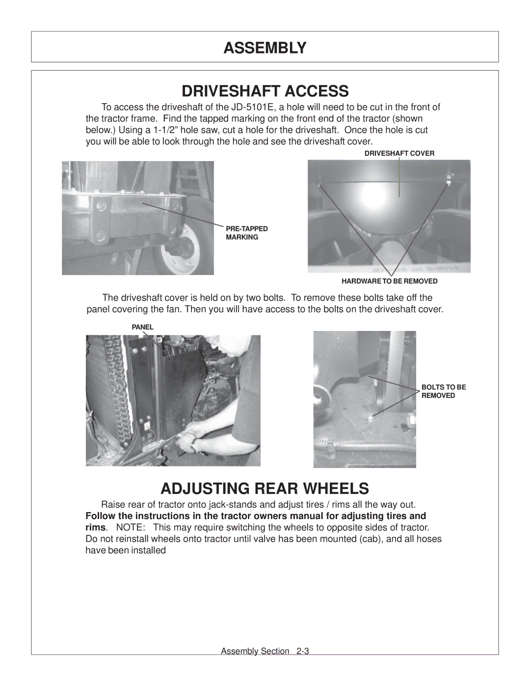
The driveshaft cover is held on by two bolts. To remove these bolts take off the panel covering the fan. Then you will have access to the bolts on the driveshaft cover.

PANEL

DRIVESHAFT COVER BOLTS TO BE

REMOVED

ADJUSTING REAR WHEELS

Raise rear of tractor onto jack-stands and adjust tires / rims all the way out.

Follow the instructions in the tractor owners manual for adjusting tires and rims. NOTE: This may require switching the wheels to opposite sides of tractor. Do not reinstall wheels onto tractor until valve has been mounted (cab), and all hoses have been installed

Assembly Section 2-3

Page 27
Image 27
Tiger JD 5083E, JD 5101E, JD 5093E manual Assembly Driveshaft Access, Adjusting Rear Wheels, Panel Bolts To Be Removed