ASSEMBLY
SWITCH BOX WIRING
Refer to the parts section for the Husco wiring schematic to hook up the switch box. Cover all wires with plastic wire wrap provided. Route the green wires along switch box bracket and cab frame to the steering wheel console. Route the rest of the wires along the base of the right hand console and up to the rubber boot in the bottom right corner in the rear window of the cab. The red and black wires will be connected to the auxillary power plug in the back of the cab. After all wiring is complete, secure all wires to the console with zip ties and push mounts. Take up most of the slack so the wires are out of the way and tighten the
Remove the panel under the steering wheel to access the wires, locate the brown wire and verify that this is the neutral safety wire with a test light or meter. Then cut the brown wire and connect a green wire from the switch box to each end of the brown wire as shown in the wiring diagram. Cut a small hole for the green wires and the wire wrap to fit through and replace the console.
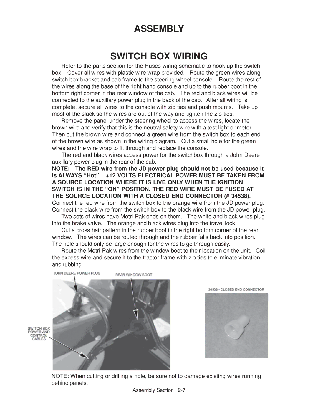
The red and black wires access power for the switchbox through a John Deere auxillary power plug in the rear of the cab.
NOTE: The RED wire from the JD power plug should not be used because it is ALWAYS “Hot”. +12 VOLTS ELECTRICAL POWER MUST BE TAKEN FROM A SOURCE LOCATION WHERE IT IS LIVE ONLY WHEN THE IGNITION SWITCH IS IN THE “ON” POSITION. THE RED WIRE MUST BE FUSED AT THE SOURCE LOCATION WITH A CLOSED END CONNECTOR (# 34538). Connect the red wire from the switch box to the orange wire from the JD power plug. Connect the black wire from the switch box to the black wire from the JD power plug.
Two sets of wires have
Cut a cross hair pattern in the rubber boot in the right bottom corner of the rear window. The wires can be routed through and the rubber falls back into position. The hole should only be large enough for the wires to go through easily.
Route the
NOTE: When cutting or drilling a hole, be sure not to damage existing wires running behind panels.
Assembly Section