06010016
Tiger Corporation
3301 N. Louise Ave Sioux Falls, SD
PARTS LISTING WITH MOUNTING AND OPERATING INSTRUCTIONS
TO THE OWNER / OPERATOR / DEALER
FORWARD
Tiger Corporation
This symbol means
TABLE OF CONTENTS
CAUTION - YOUR SAFETY IS AT RISK
ASSEMBLY / MOUNTING SECTION
SAFETY SECTION
SAFETY
SAFETY
General Safety Instructions and Practices
Practice all usual and customary safe working precautions and
DANGER
SAFETY
LEA EL INSTRUCTIVO
DANGER DANGER DANGER
SAFETY
DANGER DANGER
SG-10
SAFETY
sure you abide by the following rules
SG-23
SAFETY
SG-20
DANGER
SAFETY
DANGER
DANGER DANGER
DANGER
SAFETY
Many varied objects, such as wire, cable, rope, or chains, can become
DANGER
STOP MOWING IF PASSERSBY ARE WITHIN 100 YARDS UN- LESS
SAFETY
DANGER DANGER
DANGER
SAFETY
DANGER
DANGER
SAFETY
SEE YOUR
DEALER
“Wait a minute...Save a life!”
24028 MOWER DECK
SAFETY
LOCATION 21405 MOWER DECK 22839 MOWER DECK 22840 INSIDE OF CAB
42350 MOWER DECK 33743 INSIDE OF CAB
SAFETY
LOCATION 10” x 5.5” MOWER DECK 18.25” x10” HYDRAULIC TANK
6T3219 INSIDE OF CAB 6T3220 FRONT PUMP MOUNT
SAFETY
LOCATION 42399 MOWER DECK 42400 MOWER DECK 6T3217 MOWER DECK
6T3223 INSIDE OF CAB 6T3224 MOWER DECK 6T3230 INSIDE OF CAB
SAFETY
LOCATION 6T3221 INSIDE OF CAB 6T3222 INSIDE OF CAB
6T3236 MOWER DECK HYDRAULIC TANK 6T3243 INSIDE OF CAB
SAFETY
LOCATION 6T3233 HYDRAULIC TANK 6T3234 INSIDE OF CAB
SAFETY
34852 HYDRAULIC TANK 06550054 ON MOWER HEAD
DESCRIPTION
SAFETY
DRILLING HOLES INTO UNKNOWN AREAS, wires and other parts may
50023
This Act Seeks
SAFETY FEDERAL LAWS AND REGULATIONS
Employer-Employee Operator Regulations
DUTIES
SAFETY
Side & Rear flail Safety Section
ASSEMBLY SECTION
Assembly Section
CRANKSHAFT ADAPTER
ASSEMBLY
TRACTOR PREPARATION
DRIVESHAFT COVER PRE-TAPPED MARKING HARDWARE TO BE REMOVED
ASSEMBLY DRIVESHAFT ACCESS
ADJUSTING REAR WHEELS
PANEL BOLTS TO BE REMOVED
ASSEMBLY WHEEL SPACER WITH WHEEL WELL TANK
DRIVESHAFT COUPLER - LOADER
ASSEMBLY AXLE BRACE
HYDRAULIC TANK INSTALLATION
ASSEMBLY POLYCARBONATE SAFETY WINDOW
VALVE MOUNTING
ASSEMBLY SWITCH BOX WIRING
SELECTIVE CONTROL VALVE SCV
ASSEMBLY MAIN FRAME MOUNTING
HUSCO VALVE PLUMBING SCV ONLY UNITS
ASSEMBLY HUSCO VALVE PLUMBING WITH MID-MOUNT VALVE
MID-MOUNT VALVE
ASSEMBLY CABLE CONTROL LEVER STAND SCV ONLY UNITS
ASSEMBLY CABLE CONTROL LEVER STAND
WINDOW ROUTING
SECOND HOLE
ASSEMBLY HOSE AND CABLE ROUTING
FIRST HOLE
Secure hoses together with zip ties wherever loose. Wrap the hoses between the main boom and secondary boom with the yellow hose cover, secure with black string provided. Where hoses may contact the frame or other edges, wrap with split hose and secure with hose clamps or zip ties. On non cab units the pressure and return hoses from the control valve will also need to be routed inside the protective clear hose wrap. Cover the valve, valve fittings with the yellow hose cover and secure with black string provided
HOSE COVERING
ASSEMBLY
INSTALLING NATIONAL PIPE FITTINGS
ASSEMBLY FRONT PUMP MOUNTING
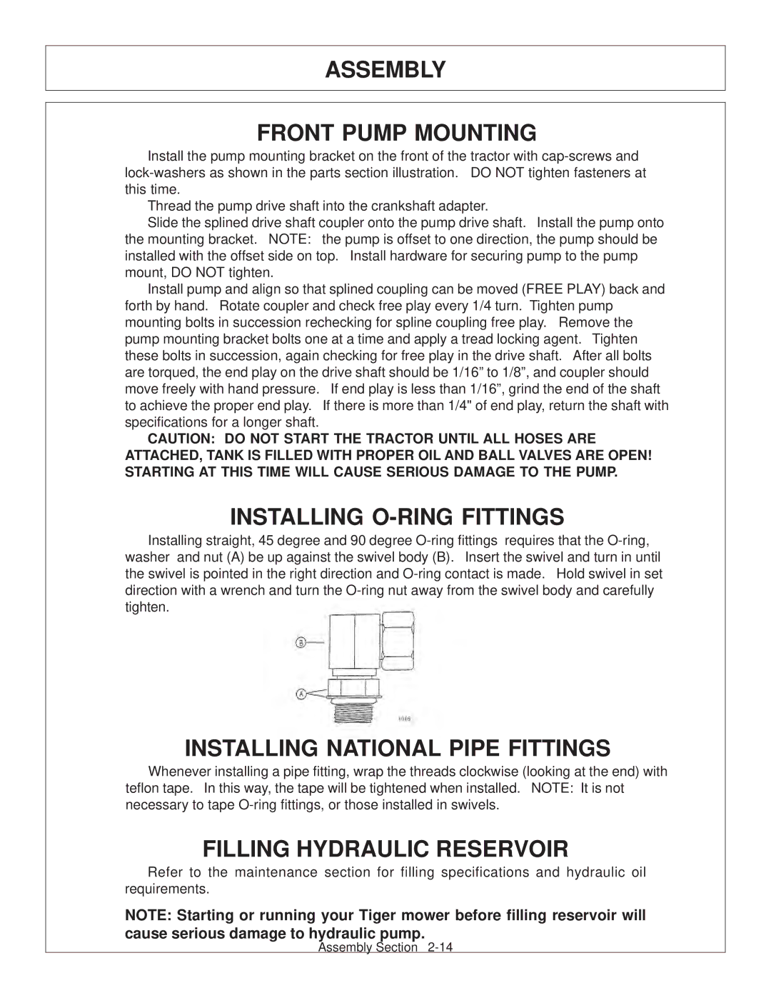
INSTALLING O-RING FITTINGS
FILLING HYDRAULIC RESERVOIR
ASSEMBLY MOTOR SOLENOID VALVE MOUNTING
CONTINUOUS DUTY SOLENOID SWITCH OPTIONAL
ASSEMBLY
COMBO LIFT DRAFT BEAM INSTALLATION
DRAFT BEAM MOUNTING
Install ½” O-ring breather into butt port of inboard cylinder. Install fittings in the rod end of the cylinder according to the diagram in the commons section. These fittings should be positioned to face the butt end of the cylinder
ASSEMBLY
DECK MOUNTING
LIFT CONTROL FEEDLINES
Check that all grease zerks have been installed in the draft beams pivot arm, left linkage arm, right linkage arm, and cylinder mounting ears
ASSEMBLY TRAVEL LOCK MOUNTING
CHECK FOR FLUID LEAKS
ASSEMBLY DECK / MOTOR FEEDLINE
STOP BOLT ADJUSTMENT
In order to prevent interference with mounted equipment, the front wheels on a 4WD 5101E tractor will have to be adjusted to approximately 64” center to center distance as shown below. Please refer to your John Deere Maintenance Manual to see the correct rim and tire configuration to achieve this. Double check the wheel spacing after adjustment by oscillating and turning the tires fully to check for any interference
4WD FRONT TIRE ADJUSTMENT
ASSEMBLY
ASSEMBLY FINAL PREPARATION FOR OPERATION
MOWER TESTING
ASSEMBLY
Assembly Section
OPERATION SECTION
OPERATION
OPERATION
OPERATION STARTING TRACTOR AND MOWER
CONTROL LOCATION AND FUNCTIONS
The rear mower height is controlled with the 3-point hitch control lever. Follow the instructions for this control is the tractor operators manual. The tilt of the rear mower is controlled with the third spool if the lift valve and is coordinated as shown above
MOWER OPERATION
OPERATION
OPERATION
Transporting unit by flatbed trailer
OPERATION TRANSPORTING MOWER
Transporting under the units own power
Next, switch the hose ends and reconnect to form two separate closed loops, see diagram below. Disconnect the lift cable from the head and secure the loose end back onto the cable with the cable clevis. Remove the keeper bolt and draft beam outer pivot pin. Separate the mower head from the tractor. Now reinstall the pivot pin and keeper bolts into the draft beam to prevent loss. OPEN THE BALL VALVES ON THE HYDRAULIC RESERVOIR BEFORE STARTING TRACTOR AGAIN! Serious damage will be caused if tractor is started with the ball valves closed
OPERATION
OPERATION
Side & Rear Flail Operation Section
DO NOT OPERATE an UNSAFE TRACTOR or MOWER
Flail Mower PRE-OPERATION Inspection
Tractor ID# Make Date Shift
OPERATION INSPECTION SHEETS
Tractor ID# Make Date Shift
TRACTOR PRE-OPERATION Inspection
OPERATION
DO NOT OPERATE an UNSAFE TRACTOR or MOWER
DO NOT OPERATE an UNSAFE TRACTOR or FRONT END LOADER
FRONT END LOADER PRE-OPERATION Inspection
Mower ID# Make Date Shift
OPERATION
Tractor ID# Make Date Shift
OPERATION
TRACTOR PRE-OPERATION Inspection
DO NOT OPERATE an UNSAFE TRACTOR or FRONT END LOADER
MAINTENANCE SECTION
MAINTENANCE
MAINTENANCE
MAINTENANCE PRECAUTIONS
BREAK IN PERIOD
Tiger Mowers are designed for high performance and rugged durability, yet with simplified maintenance. The purpose of this section of the manual is to help the operator in the regular servicing of the mower. Regular maintenance at the intervals mentioned will result in the maximum efficiency and long life of the Tiger Mower
SERVICE
MAINTENANCE REGULAR MAINTENANCE
DAILY OR EVERY 8 HOURS
COMMENTS
SERVICE
MAINTENANCE WEEKLY OR EVERY 50 HOURS
TROUBLE SHOOTING
SYMPTOMS
Oil Temperature rises
MAINTENANCE
SYMPTOMS
CAUSE
MAINTENANCE
Motor will not work
MAINTENANCE TORQUE SPECIFICATIONS
Description
MAINTENANCE LUBRICATION RECOMMENDATIONS
General Specification
Application
GRAFFITI REMOVAL
MAINTENANCE POLYCARBONATE CARE & MAINTENANCE
CLEANING THE SUPERCOAT HARD-COAT
MAINTENANCE
DETAILED MAINTENANCE
RECOMMENDED FILLING INSTRUCTIONS FOR HYDRAULIC RESERVIORS
REPLACEING IN-TANK HYDRAULIC FILTER
HEAD BOWL
MAINTENANCE DETAILED MAINTENANCE
REPLACEING HIGH PRESSURE HYDRAULIC FILTER ELEMENT
GREASING P.T.O. SHAFTS
MAINTENANCE GREASING INNER AND OUTER DRAFT BEAM PIVOT POINTS
GREASING THE UPPER AND LOWER SHEAVES
MAINTENANCE GREASING INNER AND OUTER DRAFT BEAM PIVOT POINTS
Locate the grease zerks on the inner and outer draft beam pivot bosses. Inject Lithium-Complex Extreme Pressure grease conforming to NLGI2-ISO 320 specifications into each zerk until grease protrudes from joints. Grease all pivots
GREASING PUMP DRIVE SHAFT COUPLER
MAINTENANCE GREASING THE REAR DRIVE BEARING AND
EXTENSION COUPLER SHAFT
MAINTENANCE
ADJUSTING THE CABLE LIFT
DRIVE SHAFT YOKE, U-JOINT & STUB SHAFT
With engine stopped, inject Lithium-Complex extreme pressure grease conforming to NLGI2-ISO 320 specifications into universal joints and slip yoke untill grease appears at the seal. Grease them daily or every 8 hours
MAINTENANCE
ADJUSTING THE CUTTING HEIGHT
ADJUSTING STANDARD DUTY CUT HEIGHT
MAINTENANCE BALL VALVES
GREASING CUTTER SHAFT - FLAIL MOWERS
MAINTENANCE ROSTA TENSIONER
ROSTA ARM
Used Belt 12 to 20 pounds
MAINTENANCE TENSIONER MEASUREMENT PROCEDURE
Deflection Force Values - Standard Duty New Belt 20 to 25 pounds
IDLER TENSIONING
GREASING GROUND ROLLER SHAFT - FLAIL
GREASING THE IDLER TENSION ARMS
MAINTENANCE
For standard cut on the mechanically driven rear flail mower, adjust so that the spring washer is flush with the spring guide as shown below
REVERSING MOWER ROTATION OF SIDE AND REAR FLAIL MOWERS
MAINTENANCE
MAINTENANCE
Reinstall the idler arm and pivot pin. The pivot pin is installed into the hole in the pivot bracket closest to the idler pulley. When assembling for standard cut rotation, the idler arm is installed with the idler pulley toward the front of the mower with the pivot pin in the front hole. When assembling for reverse rotation, with smooth cut knives, the idler arm is installed with the idler pulley toward the rear of the mower with the pivot pin in the rear hole
continued on next page
REVERSING MOWER ROTATION REAR MECHANICAL DRIVEN FLAIL MOWERS
MAINTENANCE
MAINTENANCE
The sprockets must be aligned and spaced approximately 3/8” apart. When changing from standard cut to smooth cut rotation, a spacer plate may have to be installed between the gear box and the frame. When changing from smooth cut to standard cut rotation the spacer plate is to be omitted. Install the chain for the chain coupling. If there is any binding, or no free movement in the chain, the bearing next to the coupler may be shimmed as required to eliminate the chain binding
KNIFE BOLTS OR NUTS
50” BOOM FLAIL KNIFE REPLACEMENT
MAINTENANCE
Knives should not be welded on for any reason
MAINTENANCE 63” BOOM FLAIL KNIFE REPLACEMENT
STANDARD OR HEAVY DUTY SIDE OR REAR FLAIL KNIFE REPLACEMENT
Knives should not be welded on for any reason
RECOMMENDED FILLING INSTRUCTIONS FOR REAR FLAIL GEAR BOX
MAINTENANCE
MAINTENANCE CUTTERSHAFT BEARING REPLACEMENT
Side & Rear flail Maintenance Section
MAINTENANCE DAILY MAINTENANCE SCHEDULE
The following services should be performed daily or every 8 hours
PARTS SECTION
JD 5101E - SIDE FLAIL MOWER
3301 N. Louise Ave Sioux Falls, SD
PARTS ORDERING GUIDE
Tiger Corporation
Direct any questions regarding parts to
SECTION
PARTS SECTION TABLE OF CONTENTS
ASSEMBLY
TRACTOR SPECIFIC PARTS
TRACTOR MOUNT KIT - MAIN FRAME 5101E
5101E TSF Parts Section
06700090
TRACTOR MOUNT KIT - MAIN FRAME 5101E
DESCRIPTION
AVAIL
TRACTOR MOUNT KIT - HYDRAULICS 5101E
5101E TSF Parts Section
6T3200
TRACTOR MOUNT KIT - HYDRAULICS 5101E
DESCRIPTION
SPLIT HOSE NOT SHOWN
TRACTOR MOUNT KIT - MAIN FRAME 5101E - LOADER
5101E TSF Parts Section
06700091
TRACTOR MOUNT KIT - MAIN FRAME 5101E - LOADER
DESCRIPTION
AVAIL
TRACTOR MOUNT KIT - HYDRAULICS 5101E - LOADER
5101E TSF Parts Section
REFER TO MAIN FRAME PARTS
TRACTOR MOUNT KIT - HYDRAULICS 5101E - LOADER
DESCRIPTION
REFER TO MAIN FRAME PARTS
TRACTOR MOUNT KIT - WHEEL WELL TANK
5101E TSF Parts Section
06700091
TRACTOR MOUNT KIT - WHEEL WELL TANK
DESCRIPTION
AVAIL
TRACTOR MOUNT KIT - HYDRO, WHEEL WELL TANK
5101E TSF Parts Section
BRAKE VALVE - REFER TO MAIN FRAME PARTS
TRACTOR MOUNT KIT - HYDRO, WHEEL WELL TANK
DESCRIPTION
AXLE BRACE,RH - REFER TO MAIN FRAME PARTS
CABLE CONTROLS - SCV ONLY
DESCRIPTION
CABLE CONTROLS - WITH MID-MOUNT VALVE
DESCRIPTION
LIFT VALVE - CABLE CONTROL, CAB
5101E TSF Parts Section
VLV,CHECK,W/.06 ORF,1/2MORx3/8
LIFT VALVE - CABLE CONTROL, CAB
DESCRIPTION
POLYCARBONATE SAFETY WINDOW - 5101E, CAB
DESCRIPTION
RING,SPACER,WHEEL,JD
WHEEL SPACER
DESCRIPTION
5101E TSF Parts Section
COMMON SIDE FLAIL - STANDARD DUTY
PARTS SECTION
SECTION
TABLE OF CONTENTS
ASSEMBLY
SPECIFIC PARTS
3301 N. Louise Ave Sioux Falls, SD
PARTS ORDERING GUIDE
Tiger Corporation
COMBO DRAFT BEAM
Side Flail Standard Duty Common Section
1. ITEM 30 IS USED ON THE GLAND END OF ITEM 2 AS NEEDED
COMBO DRAFT BEAM
DESCRIPTION
2. ORIENTATION OF ITEMS 4,5 & 6 ARE CRITICAL
STD DUTY 63” SIDE FLAIL, STANDARD ROTATION - COMBO
Side Flail Standard Duty Common Section
CUTTERSHAFT ASSY,STANDARD22, 23, 24, 25
63” SIDE FLAIL, STANDARD ROTATION - COMBO
DESCRIPTION
STD DUTY 63” SIDE FLAIL, REVERSE ROTATION - COMBO
Side Flail Standard Duty Common Section
CUTTERSHAFT ASSY,STANDARD 22, 23, 24, 25
63” SIDE FLAIL, REVERSE ROTATION - COMBO
DESCRIPTION
STD DUTY 75” SIDE FLAIL, STANDARD ROTATION - COMBO
Side Flail Standard Duty Common Section
STD DUTY 75” SIDE FLAIL, STANDARD ROTATION - COMBO
DESCRIPTION
STD DUTY 75” SIDE FLAIL, REVERSE ROTATION - COMBO
Side Flail Standard Duty Common Section
75” SIDE FLAIL REVERSE ROTATION - COMBO
DESCRIPTION
STD DUTY SIDE FLAIL DRIVE ASSEMBLY
Side Flail Standard Duty Common Section
BONNET - REFER TO HEAD PARTS
SIDE FLAIL DRIVE ASSEMBLY
DESCRIPTION
HOSE PRESSURE OF STANDARD ROTATION
HYDRAULIC LIFT CYLINDER
Side Flail Standard Duty Common Section
#6T0151R
HYDRAULIC LIFT CYLINDER
3” X 10” CYLINDER
DESCRIPTION
HYDRAULIC LIFT CYLINDER
Side Flail Standard Duty Common Section
DESCRIPTION
HYDRAULIC LIFT CYLINDER
3” X 12” CYLINDER
6T0187
RESERVOIR TANK FILTER ASSEMBLY
Side Flail Standard Duty Common Section
06505044
RESERVOIR TANK FILTER ASSEMBLY
DESCRIPTION
AVAIL
2SP HUSCO - POWER BEYOND
Side Flail Standard Duty Common Section
DESCRIPTION
2SP HUSCO - POWER BEYOND
PART NO. QTY
2SP HUSCO - POWER BEYOND
Side Flail Standard Duty Common Section
DESCRIPTION
2SP HUSCO - POWER BEYOND
PART NO. QTY
VALVE SECTION DOUBLE ACTING, CENTER SPRING
2 SP HUSCO - LOAD SENSE
Side Flail Standard Duty Common Section
2 SP HUSCO - LOAD SENSE
DESCRIPTION
2SP HUSCO - LOAD SENSE
Side Flail Standard Duty Common Section
2SP HUSCO - LOAD SENSE
DESCRIPTION
2SP HUSCO - POWER BEYOND
Side Flail Standard Duty Common Section
DESCRIPTION
2SP HUSCO - POWER BEYOND
PART NO. QTY
2SP HUSCO - LOAD SENSE
Side Flail Standard Duty Common Section
2SP HUSCO - LOAD SENSE
DESCRIPTION
2SP HUSCO - LOAD SENSE
Side Flail Standard Duty Common Section
2SP HUSCO - LOAD SENSE
DESCRIPTION
FRONT HYDRAULIC PUMP - HIGH PRESSURE
Side Flail Standard Duty Common Section
DESCRIPTION
PUMP ASSEMBLY 1 3/4” COMPLETE
FRONT HYDRAULIC PUMP - HIGH PRESSURE
23152
SIDE DECK MOTOR - HIGH PRESSURE
Side Flail Standard Duty Common Section
SIDE DECK MOTOR - HIGH PRESSURE
MOTOR ASSEMBLY 350 - TSF
MOTOR ASSEMBLY 350 - STD DUTY T3F
DESCRIPTION
SIDE COOLER
Side Flail Standard Duty Common Section
SIDE COOLER
DESCRIPTION
BRAKE VALVE ASSEMBLY W/ METRI PAK
DESCRIPTION
FAILURE MODE
SOLENOID BRAKE VALVE HYDRAULIC SCHEMATIC
BRAKE VALVE TROUBLESHOOTING
CHECK STEPS
BONNET REFER TO HEAD PARTS
SIDE FLAIL TRAVEL LOCK
DESCRIPTION
TRAVEL LOCK LIFT BEAM
DESCRIPTION
SWITCHBOX SERVICE PARTS
SWITCHBOX SCHEMATIC
Side Flail Standard Duty Common Section
WARRANTY SECTION
Warranty Section
Page
WARRANTY INFORMATION
THERE ARE NO WARRANTIES WHICH EXTEND BEYOND THOSE EXPRESSED HEREIN
ONE LAST WORD
SAFETY IS YOU
OPERATOR REQUIREMENTS
TO THE OWNER / OPERATOR / DEALER
OWNER REQUIREMENTS
Printed in USA Tiger Corporation