|
| 2 Troubleshooting Procedures |
Tables |
|
|
Table | Battery LED | ........................................................................................................10 |
Table | 11 |
2.1Troubleshooting Introduction
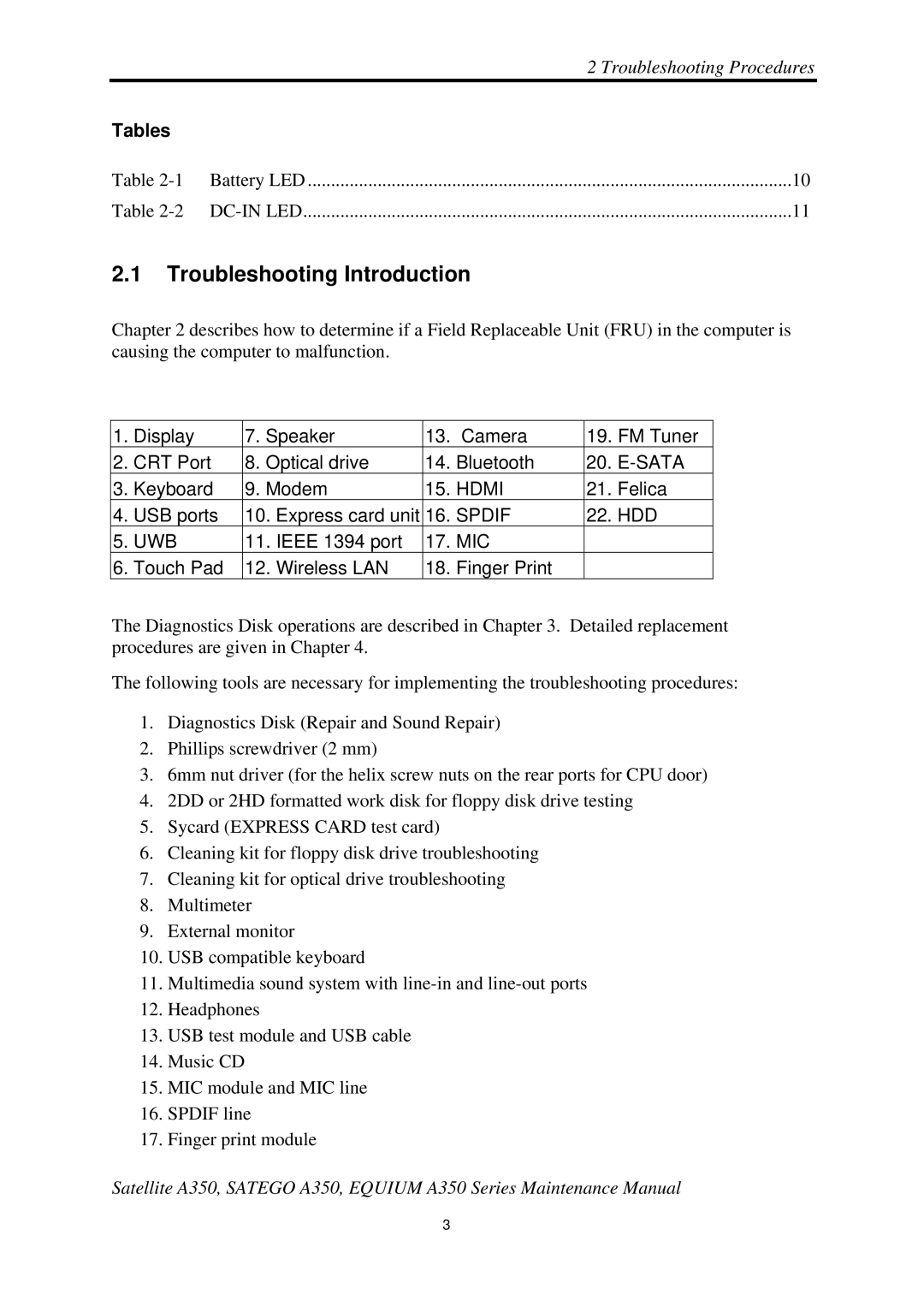
Chapter 2 describes how to determine if a Field Replaceable Unit (FRU) in the computer is causing the computer to malfunction.
1. | Display | 7. | Speaker | 13. | Camera | |
2. | CRT Port | 8. | Optical drive | 14. | Bluetooth | |
3. | Keyboard | 9. | Modem | 15. | HDMI | |
4. | USB ports | 10. | Express card unit | 16. | SPDIF | |
5. | UWB | 11. | IEEE 1394 port | 17. | MIC | |
6. | Touch Pad | 12. | Wireless LAN | 18. | Finger Print | |
19.FM Tuner
20.
21.Felica
22.HDD
The Diagnostics Disk operations are described in Chapter 3. Detailed replacement procedures are given in Chapter 4.
The following tools are necessary for implementing the troubleshooting procedures:
1.Diagnostics Disk (Repair and Sound Repair)
2.Phillips screwdriver (2 mm)
3.6mm nut driver (for the helix screw nuts on the rear ports for CPU door)
4.2DD or 2HD formatted work disk for floppy disk drive testing
5.Sycard (EXPRESS CARD test card)
6.Cleaning kit for floppy disk drive troubleshooting
7.Cleaning kit for optical drive troubleshooting
8.Multimeter
9.External monitor
10.USB compatible keyboard
11.Multimedia sound system with
12.Headphones
13.USB test module and USB cable
14.Music CD
15.MIC module and MIC line
16.SPDIF line
17.Finger print module
Satellite A350, SATEGO A350, EQUIUM A350 Series Maintenance Manual
3
