13 Operator Interface
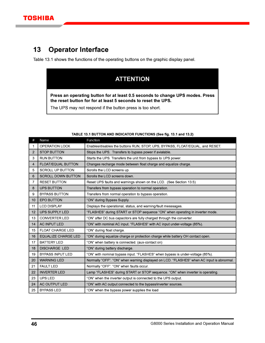
Table 13.1 shows the functions of the operating buttons on the graphic display panel.
ATTENTION
Press an operating button for at least 0.5 seconds to change UPS modes. Press the reset button for for at least 5 seconds to reset the UPS.
The UPS may not respond if the button press is too short.
Table 13.1 Button AND iNDICATOR functions (See fig. 13.1 and 13.2)
# | Name | Function |
1 | OPERATION LOCK | Enables/disables the buttons RUN, STOP, UPS, BYPASS, FLOAT/EQUAL, and RESET. |
2 | STOP Button | Stops the UPS. Transfers to bypass power if avialable. |
3 | RUN Button | Starts the UPS. Transfers the unit from bypass to UPS power. |
4FLOAT/EQUAL Button Changes recharge mode between float charge and equalize charge.
5 | SCROLL UP Button | Scrolls the LCD screens up. |
6 | SCROLL DOWN Button | Scrolls the LCD screens down. |
|
|
|
7 | RESET Button | Reset UPS faults and warnings shown on the LCD. (See Section 13.5) |
8 | UPS Button | Transfers from bypass operation to normal operation. |
9 | BYPASS Button | Transfers from normal operation to bypass operation. |
10 | EPO Button | “ON” during Bypass Supply. |
|
|
|
11 | LCD Display | Displays the operational, status, and warning/fault messsages. |
12 | UPS SUPPLY LED | “FLASHES” during START or STOP sequence “ON” when operating in inverter mode. |
13 | CONVERTER LED | “ON” after DC bus capacitors are fully charged through the converter. |
14 | AC INPUT LED | “ON” with nominal AC input. “FLASHES” with AC input |
|
|
|
15 | FLOAT CHARGE LED | “ON” during float charge. |
16 | EQUALIZE CHARGE LED | “ON” during equalize charge or protection charge while battery OH contact open. |
17 | BATTERY LED | “ON” when battery is connected. |
18 | DISCHARGE LED | “ON” during battery discharge. |
|
|
|
19 | BYPASS INPUT LED | “ON” with nominal bypass input. “FLASHES” when bypass is |
20 | WARNING LED | Normally “OFF”. “ON” when warning displayed on LCD. “FLASHES” when AC input is abnormal. |
21 | FAULT LED | Normally “OFF”. “ON” when faults occur. |
22 | INVERTER LED | Lamp “FLASHES” during START or STOP sequence. “ON” when inverter is operating. |
23 | UPS LED | “ON” when the inverter output is connected to the UPS output. |
24 | AC OUTPUT LED | “ON” with AC output connected to the bypass/inverter sources. |
25 | BYPASS LED | “ON” when the bypass power supplies the load |
46 | G8000 Series Installation and Operation Manual |
