Split Type
Contents
11-2
11-1
11-3
11-4
Original instruction
Explanation of illustrated marks
Explanation of indications
Work undertaken Protective gear worn
Indication Explanation
Electrical Shock Hazard
Confirmation of warning label on the main unit
Without first conducting these checks
Service person is allowed to do this work
Proceeding with the repair work
Discharged
Protective gloves and safety work clothing
Procedure in the ladders instructions
Telephone wires
Electric shocks, electrical leakage, smoking and/or a fire
Wires as before
Never recover the refrigerant into the outdoor unit
Refrigerant gas may catch fire
Do not use a welder in the closed room
Before opening the service panel
Service panel
Though the refrigerant gas itself is innocuous
Refrigerant leaks
Page
Declaration of Conformity
Explanations given to user
Relocation
Specifications
Copper pipe Piping
Safety Caution Concerned to New Refrigerant
Flare nut
Joint
General tools Conventional tools can be used
Tools
SM40, SM45, SM56 type SM80 type
Construction Views External Views
Page
Wiring Diagram
Concealed Duct Type
Parts name Type Specifications
Case of Connection of Wired Simple Remote Controller
Indoor Controller Block Diagram
Indoor unit #1 Heder Wireless remote controller
Case of Connection of Wireless Remote Controller
LCD
Outline of specifications Remarks
Room temp. control
Temperature in heating
Setting at shipment
Heat
Tc ≥ 60C, the fan speed increases by 1 step Temperature
Fan speed control
Outline of specifications
Heating ready is
Remarks
Tcn
Tcj
Tc n
Conditions
Mode when
Setup at shipment
Setup temperature on
Room temp. monitor
Case of wireless remote controller
Case of wired remote controller
Values of various sensors
Central
Goes on
Conditioner may stop or an error code may be displayed
When validating the save operation, the next operation
Pushed for 4 seconds or more on the remote controller
Starts with save operation valid because contents are
This function is set up at the customer’s side
MCC-1631
Indoor P.C. Board Optional Connector Specifications MCC-1631
Before troubleshooting
Summary of Troubleshooting
Troubleshooting procedure
Wired remote controller type
Wireless remote controller type
Lamp indication Check code Cause of trouble occurrence
Outline of judgment
Lamp indication Check code
Others Other than Check Code
Central control devices detected
Remote controller detected
Indoor unit detected
Error mode detected by indoor unit
Check Code List
Air conditioner
Error mode detected by outdoor unit
Operation of diagnostic function Check Status
Operation of diagnostic function Judgment and measures
E09 error
Check code E01 error
E10 error
E04 error
L09 error
E18 error
E08, L03, L07, L08 error
P30 error Central controller
L20 error
L30 error
F10 error
P10 error
CN333 CN334
P12 error
Check by tester
P19 error
Exchange to cooling cycle
Exchange to heating cycle
F01 error
F02 error
C06 error 11 model connection interface
P31 error Follower indoor unit
E03 error Master indoor unit
F29 error
TA, TC, TCJ, TE, TS, to sensor
Temperature Resistance value characteristic table
TD, TL sensor
TD, TL sensor
Position Resistance value
Part name Checking procedure
Case
Replacement procedures
C. Board for indoor unit servicing replacement procedures
Setting data read out from Eeprom
Contents
Code No. required at least
Refer to table Button for the temperature setting
Writing the setting data to Eeprom
Eeprom layout diagram
Setting data Type
Setting data Type Type name abb
Type Code No
Model Name RAV-SM∗∗∗BT-ETR
Indoor Unit
Test Run Setup on Remote Controller Wired remote controller
Wiress remote controller
D403 Red
Practical operation
LED Display on Indoor P.C. Board D501 Red
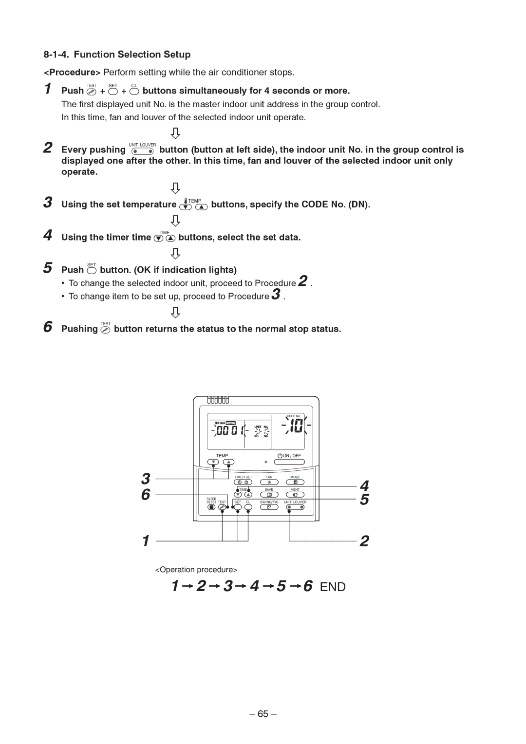
Using the set temperature
Function Selection Setup
To change the selected indoor unit, proceed to Procedure
To change item to be set up, proceed to Procedure
Description At shipment
Item No. DN table Selection of function
Description At shipment
When connected 2 remote controllers operate an idoor unit
Wireless remote controller
When connected 2 remote controllers operate the twin
Remote controller address A-B selection setting
Wireless remote controller B setup
Wireless remote controller A-B selection
Contents
Order to monitor another error history, push the set
„ Calling of error history Contents
Temperature Buttons to change the error
Pushing
Usual regular communication
„ Indoor unit power-ON sequence
Initial communication
Model connection interface wiring connection
Microprocessor block diagram
Model Connection Interface TCC-LINK adapter
Model name TCB-PCNT30TLE2
C. Board Switch SW01 Setup
Wiring Specifications
Use 2-core with no polar wire
To prevent noise trouble, use 2-core shield wire
External view of P.C. board assembly
How to set up from indoor unit side by remote controller
Address setup
Push Test + Vent buttons for 4 seconds or more
Page
Address setup procedure
Address Setup
Address Setup & Group Control Terminology
System configuration
Single
Triple Single group operation
It is not influenced by the line 2 or 3 address indoor unit
Example
Only turning on source power supply Automatic completion
Automatic Address Example from Unset Address No miswiring
Standard One outdoor unit
Multiple groups operation
Push SET + CL + Test buttons
Using timer time Buttons, set the line address
Simultaneously for 4 seconds or more
Folloer unit Push
To know the position of indoor unit body by address
Procedure
Button if the unit stops
Fan and louver of the selected indoor unit only operate
Attachment
Part name Procedure Remarks
Detachment
Electric parts
Suction panel
Cover from the projection of the side plate
Then remove the cover
Board
Box
Control P.C
Fan motor
Remove connectors for fan motor wiring
From control P.C. board
Match the fan motor with turning direction
Drain pan
Float switch
Drain pump
Attachment
Heat
Position and fix it as before, using screws
Perform works of 1
Set the heat exchanger at the original
RAV-SM406BT-E, RAV-SM456BT-E, RAV-SM566BT-E
SM456BT-E SM566BT-E
Location Description Model Name RAV
RAV-SM806BT-E
Location Description Model Name
RAV-SM406BT-TR, RAV-SM456BT-TR, RAV-SM566BT-TR
SM456BT-TR SM566BT-TR
RAV-SM806BT-TR
RAV-SM806BT-TR
SM406BT-E SM456BT-E SM566BT-E
Location Model Name RAV Description
RAV-SM1106BT-E, RAV-SM1406BT-E, RAV-SM1606BT-E
Location Description Model Name RAV SM1106BT-E
RAV-SM1106BT-TR, RAV-SM1406BT-TR, RAV-SM1606BT-TR
100
101
RAV-SM1106BT-E TR, RAV-SM1406BT-E TR, RAV-SM1606BT-E TR
Check of Concentration Limit
Toshiba Carrier Corporation