MAINTENANCE
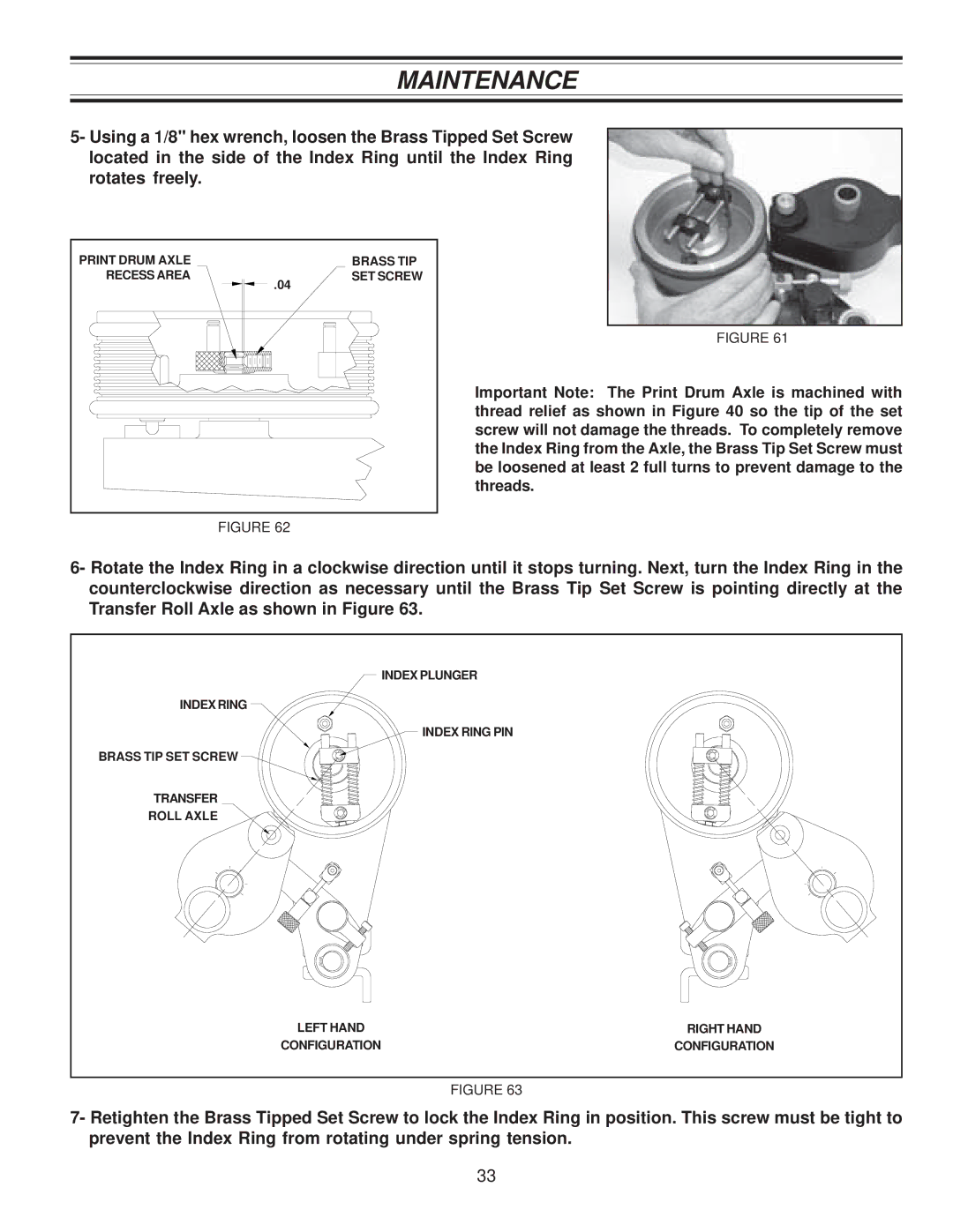
5- Using a 1/8" hex wrench, loosen the Brass Tipped Set Screw located in the side of the Index Ring until the Index Ring rotates freely.
PRINT DRUM AXLE |
| BRASS TIP |
RECESS AREA | .04 | SET SCREW |
|
|
FIGURE 61
Important Note: The Print Drum Axle is machined with thread relief as shown in Figure 40 so the tip of the set screw will not damage the threads. To completely remove the Index Ring from the Axle, the Brass Tip Set Screw must be loosened at least 2 full turns to prevent damage to the threads.
FIGURE 62
6- Rotate the Index Ring in a clockwise direction until it stops turning. Next, turn the Index Ring in the counterclockwise direction as necessary until the Brass Tip Set Screw is pointing directly at the Transfer Roll Axle as shown in Figure 63.
| INDEX PLUNGER |
INDEX RING |
|
| INDEX RING PIN |
BRASS TIP SET SCREW |
|
TRANSFER |
|
ROLL AXLE |
|
LEFT HAND | RIGHT HAND |
CONFIGURATION | CONFIGURATION |
FIGURE 63
7- Retighten the Brass Tipped Set Screw to lock the Index Ring in position. This screw must be tight to prevent the Index Ring from rotating under spring tension.
33
