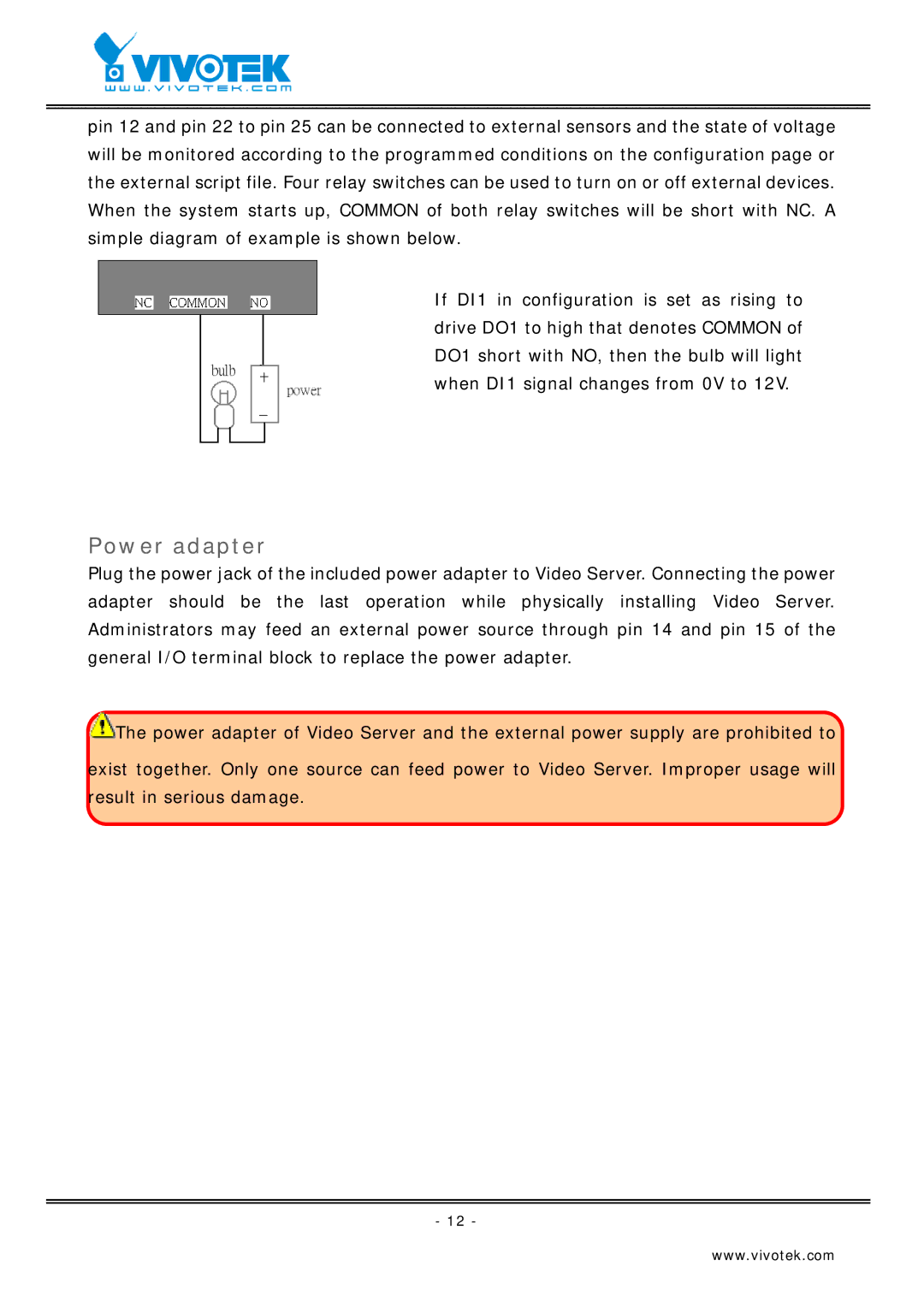
pin 12 and pin 22 to pin 25 can be connected to external sensors and the state of voltage will be monitored according to the programmed conditions on the configuration page or the external script file. Four relay switches can be used to turn on or off external devices. When the system starts up, COMMON of both relay switches will be short with NC. A simple diagram of example is shown below.
If DI1 in configuration is set as rising to drive DO1 to high that denotes COMMON of DO1 short with NO, then the bulb will light when DI1 signal changes from 0V to 12V.
Power adapter
Plug the power jack of the included power adapter to Video Server. Connecting the power adapter should be the last operation while physically installing Video Server. Administrators may feed an external power source through pin 14 and pin 15 of the general I/O terminal block to replace the power adapter.
![]() The power adapter of Video Server and the external power supply are prohibited to
The power adapter of Video Server and the external power supply are prohibited to
exist together. Only one source can feed power to Video Server. Improper usage will result in serious damage.
- 12 -
www.vivotek.com