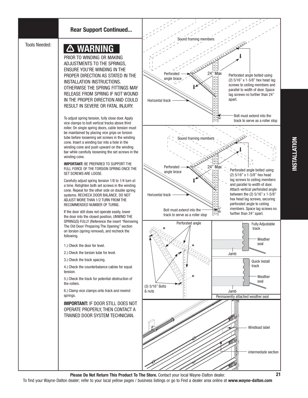
9800 specifications
Wayne-Dalton is a well-known brand in the garage door industry, offering a wide range of models designed for durability, performance, and aesthetic appeal. Among its most popular series are the 9700, 5000, 8000, 9000, and 9800, each equipped with unique features and advanced technologies to meet diverse customer needs.The Wayne-Dalton 9700 series is known for its combination of strength and insulation. This garage door is manufactured with a three-layer construction providing robust protection against the elements while offering excellent energy efficiency. The insulated steel construction can help maintain interior temperatures, making it ideal for attached garages.
The 5000 series, on the other hand, is designed for a more traditional look combined with modern performance. Featuring a lightweight design, it is made from durable materials that resist rust and corrosion. The 5000 series can be customized with different colors and styles, allowing homeowners to achieve the perfect aesthetic to enhance their property.
Moving on to the 8000 series, this model is designed for commercial applications and residential use where heavy-duty functions are necessary. It is built to withstand extreme weather conditions while providing optimal security with added strength features. The 8000 series offers smooth operation and minimal maintenance requirements, making it a great choice for those seeking reliability.
The 9000 series stands out with its stylish design and sleek finishes. This series offers advanced insulation options, coupled with numerous panel designs that provide a polished and sophisticated look. The 9000 model emphasizes both aesthetics and energy efficiency, making it a favorite among homeowners looking for a beautiful yet functional garage door.
Lastly, the 9800 series is the premium option within Wayne-Dalton’s offerings. This series is characterized by its high insulation value and thermal efficiency, thanks to its innovative construction techniques. The 9800 doors can be customized with numerous panel options and colors, delivering a luxury look while ensuring excellent performance.
In conclusion, Wayne-Dalton’s 9700, 5000, 8000, 9000, and 9800 series garage doors each feature distinctive characteristics and technologies aimed at enhancing durability, security, and aesthetics. Homeowners can find a reliable option within this range that suits their specific requirements, whether they prioritize insulation, style, or heavy-duty functionality. With Wayne-Dalton’s commitment to quality and innovation, these garage doors stand out in today’s market.

